
In this installment, we continue our beginner-friendly look at modular synth power supplies. This is Part 2 of the column series for those who find modular synth power a bit confusing. In Part 1, we covered the basics: +12V, Ground, and -12V rails, as well as what voltage and current actually mean. We even lit up a light bulb with a modular synth power supply.
This time, we will walk through +5V voltage, cases, bus boards, and AC adapters, one topic at a time.
- What About +5V? CV and Gate?
- Cases, Bus Boards, and Power Supplies
- Bus Boards
- Power Supply Units
- AC Adapters
What About +5V? CV and Gate?
In the previous article, we talked about using +12V and -12V, but some modules also use +5V. Here is the photo of the power socket terminals from last time. The +5V terminal is the third row from the top, highlighted in orange.
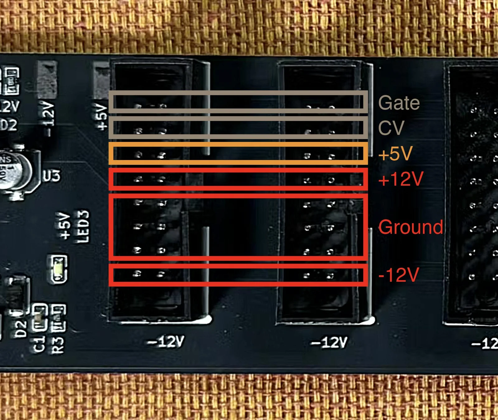
Gate is at the very top row, and CV is the second row from the top. Let’s look at each of these in turn.
+5V
This +5V terminal provides a lower voltage than the +12V we discussed last time. In electronics, +5V is a very convenient voltage level, and many ICs operate at +5V or below.
For example, USB-A and USB-B connections deliver +5V. Peripherals like those connected to a computer that work without a separate AC adapter are receiving +5V from the computer and running on it. So the components inside those peripherals are generally designed to operate at +5V or less.
In modern modular synths, digital ICs capable of advanced processing are increasingly being used. You might think, “Great, +5V sounds useful!” However, modules that actually receive +5V from the power supply are surprisingly few. Probably less than 5% of all modules.
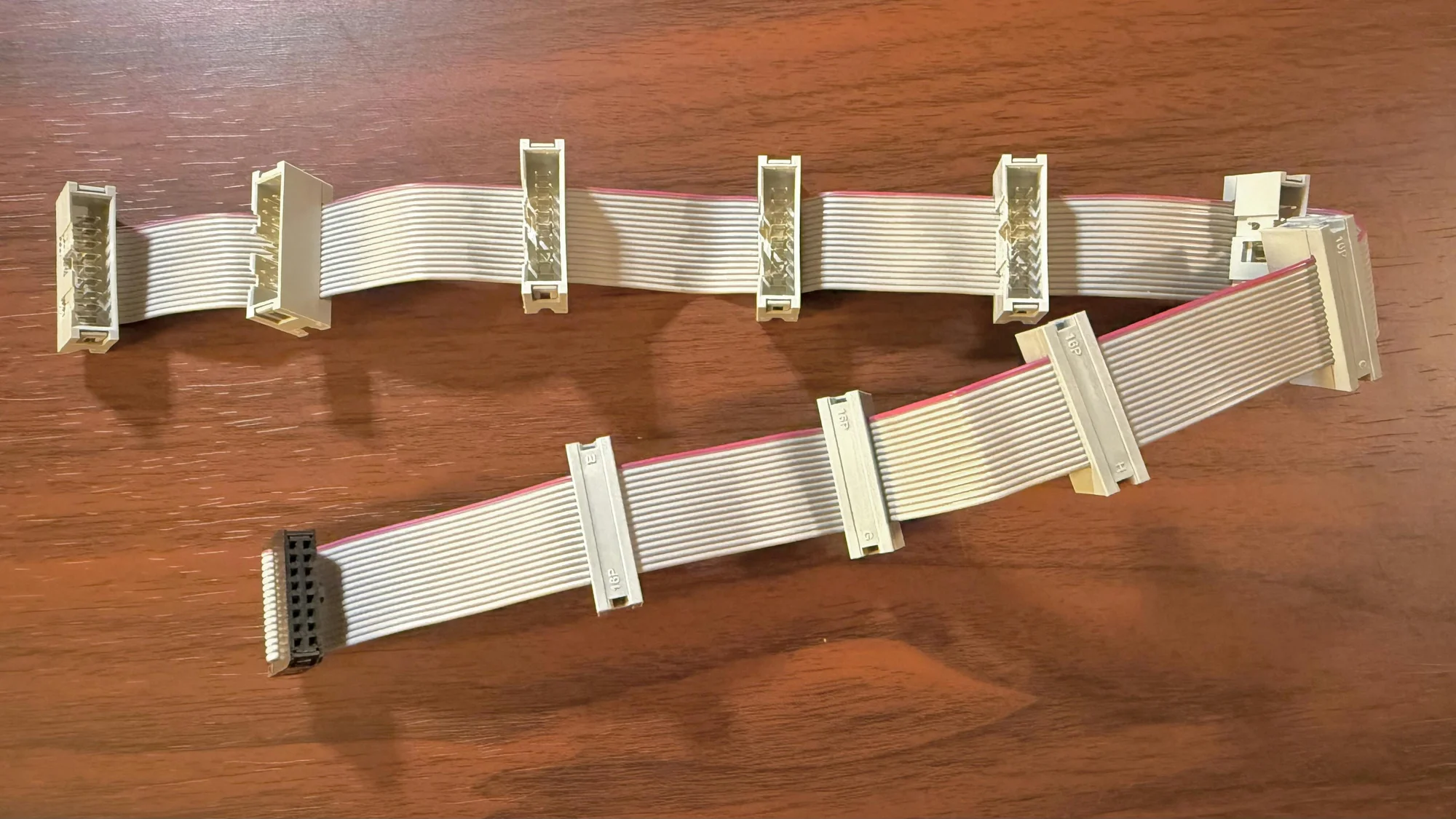
If you look at the modules you own, you will likely find that the majority use ribbon cables with a smaller connector on one side to receive power. For comparison, here is a ribbon cable with the larger 16-pin connectors on both sides, shown alongside the smaller type.
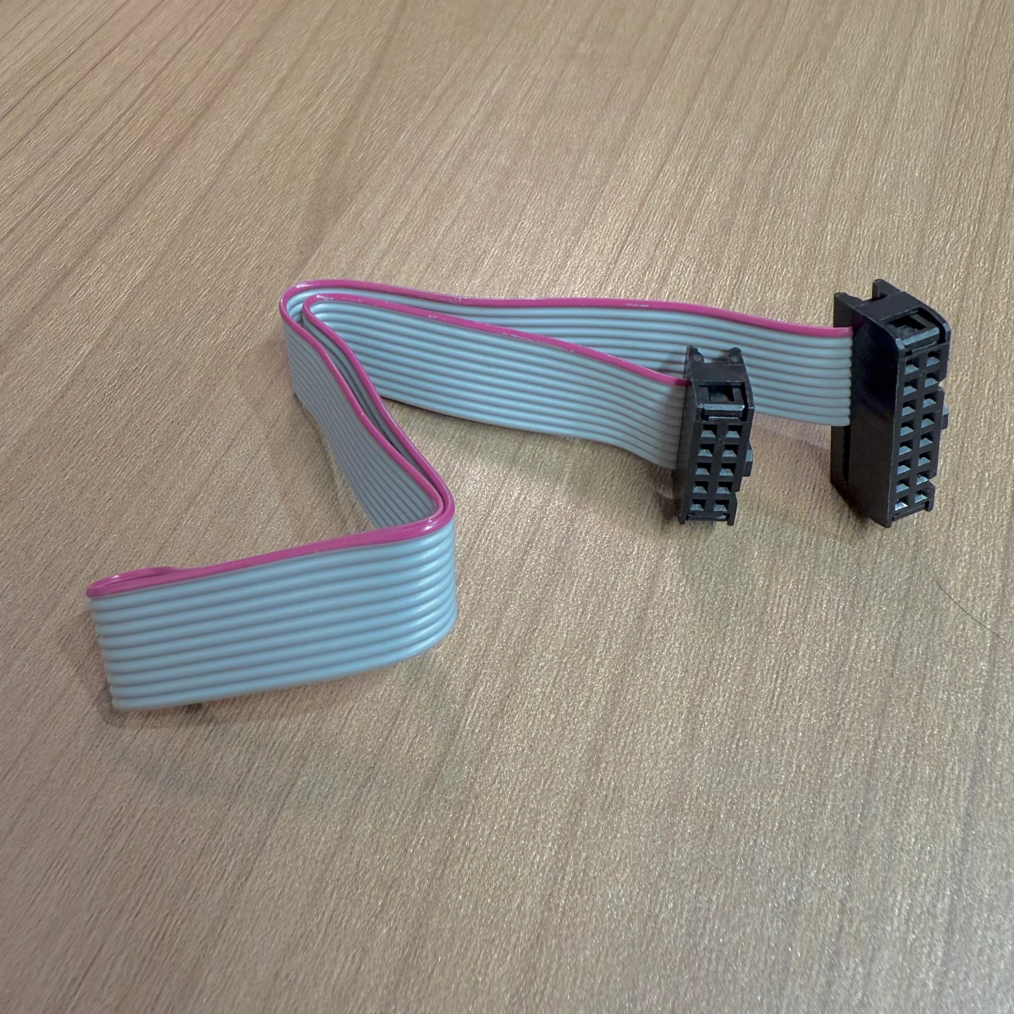
If you count the holes on the compact connector, you get 2x5 = 10 total. Going through the pin assignments from one end:
- -12V
- Ground
- Ground
- Ground
- +12V
…and that’s it. In other words, +5V is simply not being sent to these modules at all.
This does not mean these modules never use voltages of +5V or below internally. When needed, they include voltage regulation circuitry within the module itself to step down from +12V or -12V, and they are designed to operate on just those two voltages.
Wait, what? If +5V is available, why not just use it? That seems like the simple answer, but in short, because most modules are designed to use only +12V and -12V, everyone follows that convention.
On the power supply side as well, some cases and power modules do not provide +5V at all, supplying only +12V and -12V. Others do provide +5V, but with a significantly lower rated current for that rail.
So, the key takeaway: most modules in the world run primarily on +12V and -12V, and some also require +5V.
Does My Module Use +5V?
The most reliable way to check whether a module uses +5V is to visit the manufacturer’s website. You can also find mostly accurate information on ModularGrid.
CV and Gate Terminals
As shown in the photo earlier, the power connector also has CV and Gate terminals, but these are almost never used in practice. These terminals can be used to pass CV and Gate signals between modules within the same case, or to exchange digital signals for changing presets between modules.
However, as most modular synth users know, CV and Gate are almost always exchanged via patch cables nowadays. So it is enough to be aware that some modules out there do use these CV and Gate terminals on the power connector. If you ever encounter such a module, just remember that this is what those terminals are for.
Cases, Bus Boards, and Power Supplies
So, to recap: +12V and -12V are the fundamentals, and +5V is occasionally used as well.
Next, let’s take a closer look at modular synth cases. Many of you might be thinking, “Power supply? I don’t really know about that stuff — I just use whatever came with the case I bought!” And that is completely normal.
If you own a reasonably sized case, it almost certainly has a bus board installed — a board with many sockets for plugging in power ribbon cables. We sell one at our shop too, called the zudo-bus, a Takazudo original bus board. It looks like this:
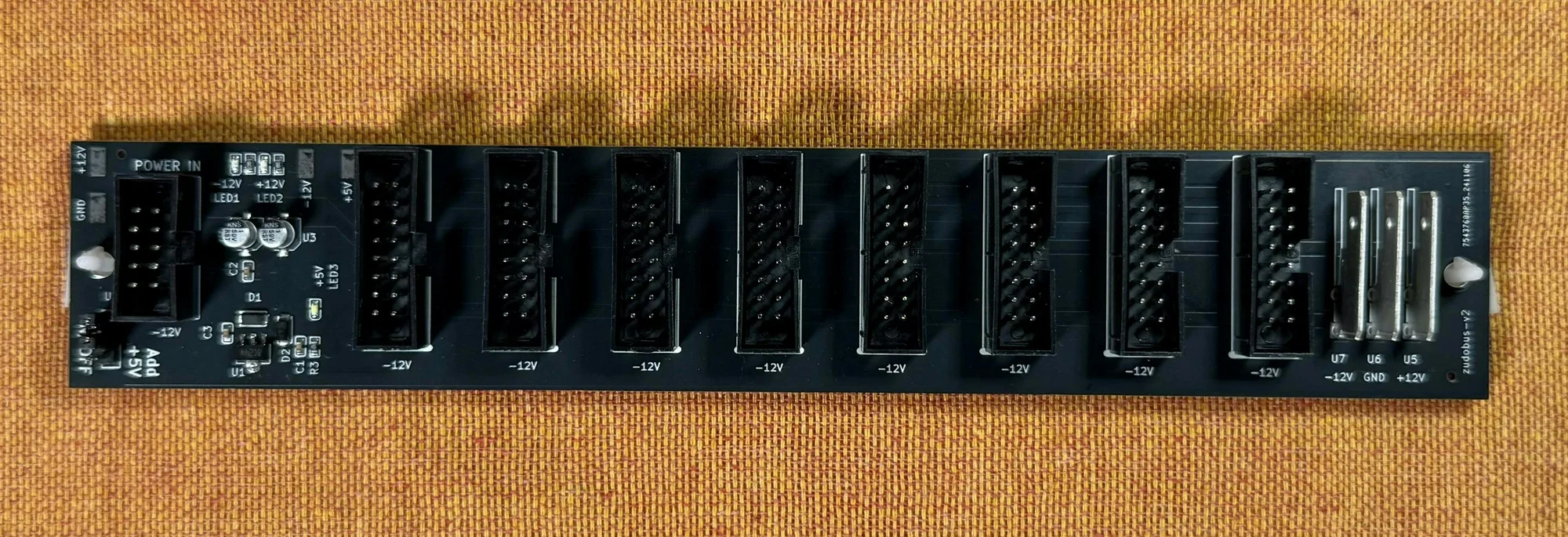
Yes, this is the thing you plug ribbon cables into.
As another example, Takazudo has an Arturia RackBrute 6U case at home, and the bus board in that case looks like this:

You can see it has connectors for many modules.
Now, here is the thing: the bus board itself does not generate electrical power. (At least not in this RackBrute 6U.)
The component that actually supplies the power for all the modules — generating the +12V, +5V, and -12V voltages — is this part:

This is called the power supply unit (PSU), the device that produces the voltages needed for a modular synth.
The key point here is that when we talk about a modular synth “case,” it often consists of three separate things working together:
- An outer enclosure that simply holds the modules
- A power supply unit (PSU)
- A bus board
If you buy a reasonably priced case, all three of these typically come as a set. But there is absolutely no problem with sourcing them separately. You could even take a spare wooden box you have lying around, mount modules in it with the right dimensions, and attach your own PSU and bus board — that is a perfectly valid way to start with modular synthesis. There are also products where the bus board and PSU come as a combined unit.
If you are just getting started with modular synths, it is completely understandable not to realize that these three are separate components that happen to be sold as a set. Understanding this distinction is a good first step.
Bus Boards
Now let’s look at bus boards in more detail. What exactly is this thing with all the power sockets?
A bus board is, using the battery-and-light-bulb analogy from last time, essentially a way to supply power to multiple light bulbs at once, like this:

Where is the bus board in this picture, you ask? It is the horizontal copper wires — the two extending from the battery.
Without these wires, every light bulb would have to be connected directly to the battery. Since light bulbs represent modules in a modular synth, doing this in a case would mean running every module’s ribbon cable directly to the PSU. But a PSU cannot have that many sockets, so the bus board handles that distribution.
When current flows to the light bulbs in this arrangement, each one receives power equally. A real bus board works the same way — it delivers current to each module in parallel. The circuit is quite simple. It is essentially the parallel circuit you might remember from elementary school science class.
As a note, with a battery and light bulbs, you only have positive and negative terminals. With a modular synth, the pins are split into +12V, Ground, -12V, +5V, Gate, and CV, and each of those pins is connected across the bus board.
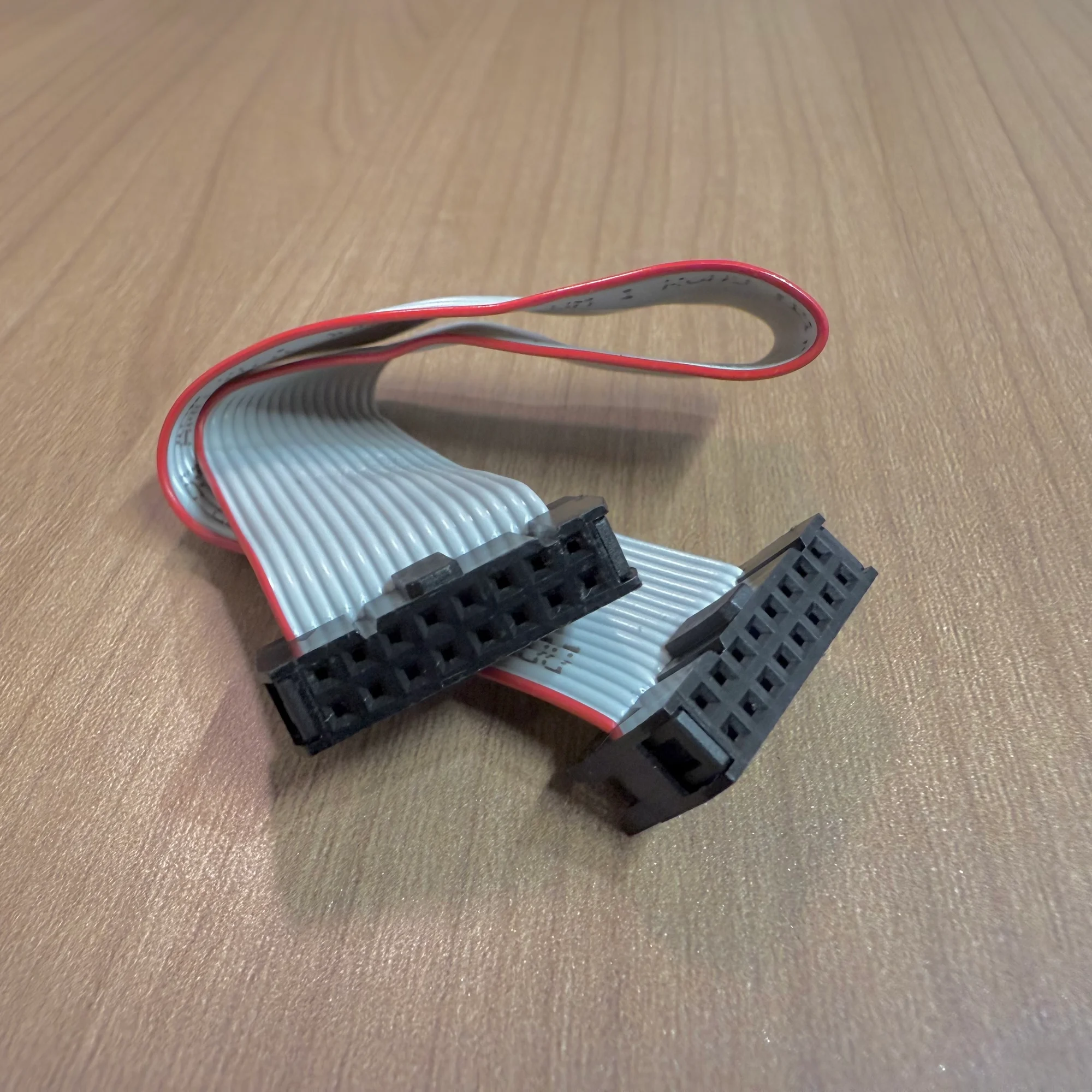
The bus board can also be replaced by what is called a flying bus cable, which looks like an octopus-wired ribbon cable. These are commonly included with relatively affordable power modules.
A flying bus cable is simply a set of conductors connecting the same pins together. Think of it as a bus board, but in cable form rather than as a PCB.
So bus boards are actually quite simple devices. One difference compared to flying bus cables is that bus boards typically include some degree of noise filtering. More carefully engineered bus boards may involve deeper research into noise reduction, but at their core, this is the role a bus board plays.
Flying Bus Cables and Current Capacity
Reading this section alone, you might think, “Well then, I’ll just go with a flying bus cable — it’s cheaper and easier to work with.” However, the copper wires in a flying bus cable are thin, so connecting too many modules can cause the total current demand to exceed what the thin wires can safely carry.
Think of a flying bus cable like a household power strip with multiple outlets chained together. Power strips have a maximum wattage rating (like 1500W), and in the same way, a flying bus cable has a limit on how much current it can carry.
Cases designed for a reasonable number of modules usually come with proper bus boards. This design choice takes the disadvantages of flying bus cables into account. Plus, having the board mounted in place is simply more convenient to work with.
Power Supply Units
We are gradually taking the case and power supply apart. Next up: the power supply unit that actually generates the electricity for your modules. The power supply unit is also called a PSU (Power Supply Unit).
In the RackBrute 6U example, the PSU is mounted as a 5HP module and connected to the bus board with a thick cable:

Relatively affordable PSUs are often designed to be mounted as a module like this.
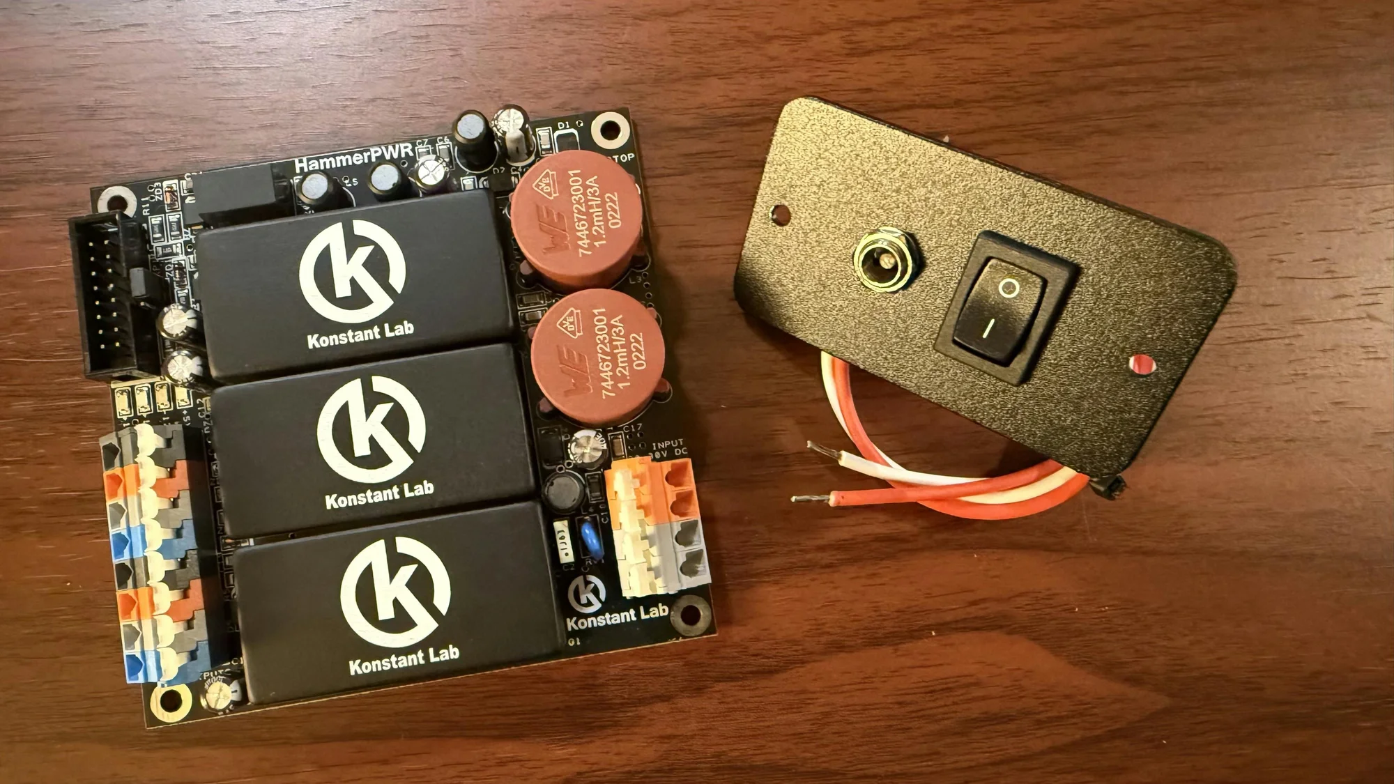
Another example from Takazudo’s collection: the HammerPWR from Konstant Lab. This PSU is sold as a standalone unit — the AC adapter and bus board are sold separately, and it is intended for people who want to build their own case setups.
Beyond these, some cases integrate the bus board and PSU into a single unit. The designs vary widely.
The PSU performs a specific job: in a typical configuration, it takes the electricity coming through an AC adapter and converts it into fixed voltages of +12V, +5V, and -12V using its internal circuitry.
Going back to the battery-and-light-bulb analogy: the battery had a positive terminal and a negative terminal. In modular synth terms, these correspond to +12V and Ground. Imagine having three such battery pairs: one for +12V and Ground, one for +5V and Ground, and one for -12V and Ground.
The diagram below illustrates the signal path from PSU to bus board to ribbon cable to module. The yellow and pink arrows show the direction of current flow. The green parts are ribbon cables, and the blue lines are the bus board.

The pink arrows are slightly tricky: for the -12V rail, current flows in the reverse direction, going from Ground back toward the PSU. You can refer to the previous article for more detail on this concept.
The PSU itself performs this voltage conversion and, through the bus board or flying bus cable, supplies the appropriate voltage and current to each module.
PSU Heat Generation
You may notice that the PSU gets fairly warm during operation. This is due to the characteristics of the components used for voltage conversion. For instance, one component used to produce a stable voltage is a linear regulator such as the LM7812, which outputs a fixed +12V.
It is a clever component, but it needs to receive around +14V to +18V to operate. It takes a slightly higher voltage and shaves off the excess to produce a clean, stable +12V output. However, the excess voltage is dissipated as heat. Because components like these are used in the PSU, it can get hot. Since most electronic components degrade or fail at high temperatures, heat sinks are commonly paired with these components. The metal shroud visible on the RackBrute 6U’s PSU in the photos serves this purpose.
AC Adapters
The PSU almost always receives its electricity via an AC adapter. It takes power from a household outlet, which in Japan provides 100V. Meanwhile, the voltages used by modular synth modules are +12V, +5V, and -12V. Compared to these, 100V is far too high.
Most PSUs are not designed to receive 100V directly. Simply put, 100V is unnecessary for them, and handling it directly is somewhat dangerous. The voltage a PSU actually needs is typically around +15V to +20V. The PSU receives this lower, adjusted voltage and converts it through its circuitry into +12V, +5V, and -12V.
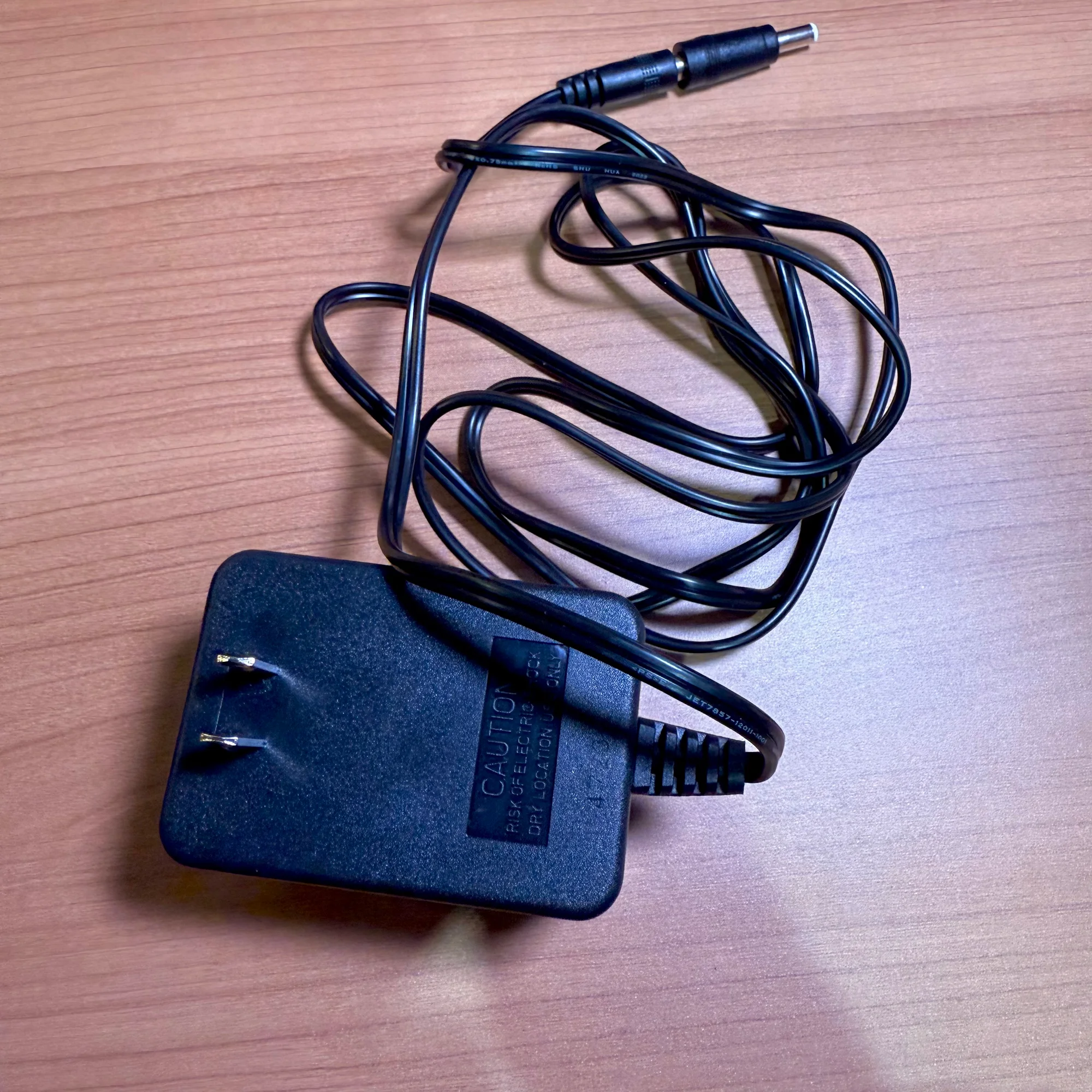
So what converts the 100V down to around 15V? That is the AC adapter. You have probably seen those bulky brick-like devices attached to the cables of computers and appliances, or noticed how large some AC adapters are and wished they were smaller. Those bricks are reducing the high 100V down to a voltage that the device can use. Without that brick, the device itself would need internal circuitry to step down the voltage.
So if you have ever worried about getting electrocuted when connecting or disconnecting your modular synth, rest assured: the voltage flowing through it is not the high 100V from the wall outlet, so there is no need to be overly fearful. *
Consider this for perspective: a AA battery is 1.5V, USB-A/B is 5V, and the LED light we used in Part 1 and a Wi-Fi router run on about 12V. Devices that use the full 100V directly are things like space heaters and hair dryers.
What you should be cautious about with modular synths is not so much electric shock, but rather damaging the modules themselves. If you touch exposed IC pins or traces with damp hands while the circuit is powered on, unintended current paths can form and destroy delicate components. As mentioned earlier, many ICs operate at 5V or below — if 12V flows into them, they will break. This is because the internal components are not rated for that voltage. So always make sure to turn off the power before installing or removing modules.
As a side note, Takazudo once plugged a small light bulb directly into a wall outlet as a curious child. It flashed incredibly bright for an instant, then burned out — quite a shock. Looking back, that was genuinely dangerous. Please do not try this at home. It just goes to show that light bulbs, too, break when subjected to excessive voltage.
* There are PSUs that receive 100V directly without an AC adapter. If you use one of those, you need to handle it with extra care.
This time we covered +5V, cases, bus boards, power supply units, and AC adapters.
The power supply intro series continues…! Next time, we plan to discuss current draw.
The next installment is ready. Please see below.