This article explains how to assemble the 10BOX JuBako.
The 10BOX JuBako is a DIY modular synth case available through early access on Takazudo Modular: Panels.
- Required Tools
- Structural Overview
- Assembly Steps
- 1. Rail Frame Assembly
- 2. Lid Assembly
- 3. Base Assembly Part 1: Outer Box
- 4. Base Assembly Part 2: Attaching the Rails
- 5. Stand Assembly
Required Tools
The following tools are needed for assembly. Please have these ready before you begin.
- Hex wrench set (e.g., Amazon: Hex wrench set, 9-piece)
- Spanner set (e.g., Amazon: Mini spanner set)
- Phillips screwdriver (e.g., Amazon: Screwdriver set / Amazon: Electric screwdriver set)
- Pliers (optional) (e.g., Amazon: Pliers set)
Regarding screwdrivers: this case requires tightening nearly 70 screws in total, so an electric screwdriver is highly recommended to make the process much easier. (It also makes mounting modules to the case rails much more convenient.)
Structural Overview
Before we get into the assembly steps, it helps to understand the overall structure of the 10BOX JuBako.
This case is composed of four main parts:
- Rail frame
- Lid
- Base
- Stand (shallow version only)
Each part is assembled separately and then combined into a single unit.
Let’s briefly describe each part.
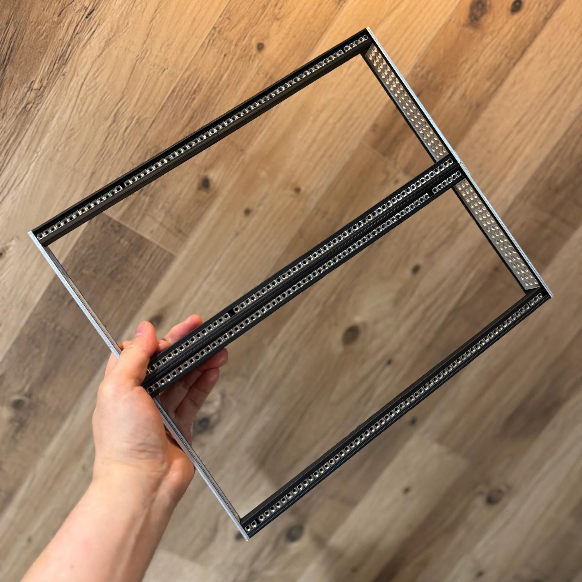
1. Rail Frame
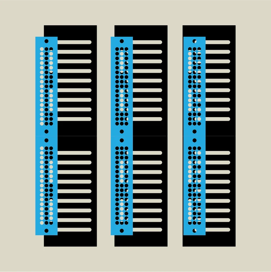
First is the rail section. The 10BOX rail frame uses the zudo-rail, a versatile rail kit sold at our shop.
The zudo-rail comes in two length variants (40HP and 60HP) and several build variants (Lite, Nuts, Dual, and Metal). The 10BOX includes a 60HP rail in one of these variants.
The aluminum side frames of the rail kit have numerous holes. These are used with screws, washers, and nuts to attach the rail frame to the holes on the sides of the outer box.
2. Lid
The 10BOX comes with a lid. It is included as a separate part from the base.
The lid is assembled by combining panels with L-brackets, similar to the case itself. The front and rear panels of the lid have a step-down edge that sits inside the gap between the base’s front/rear panels and the rail frame when the lid is placed on top, providing a snug fit.
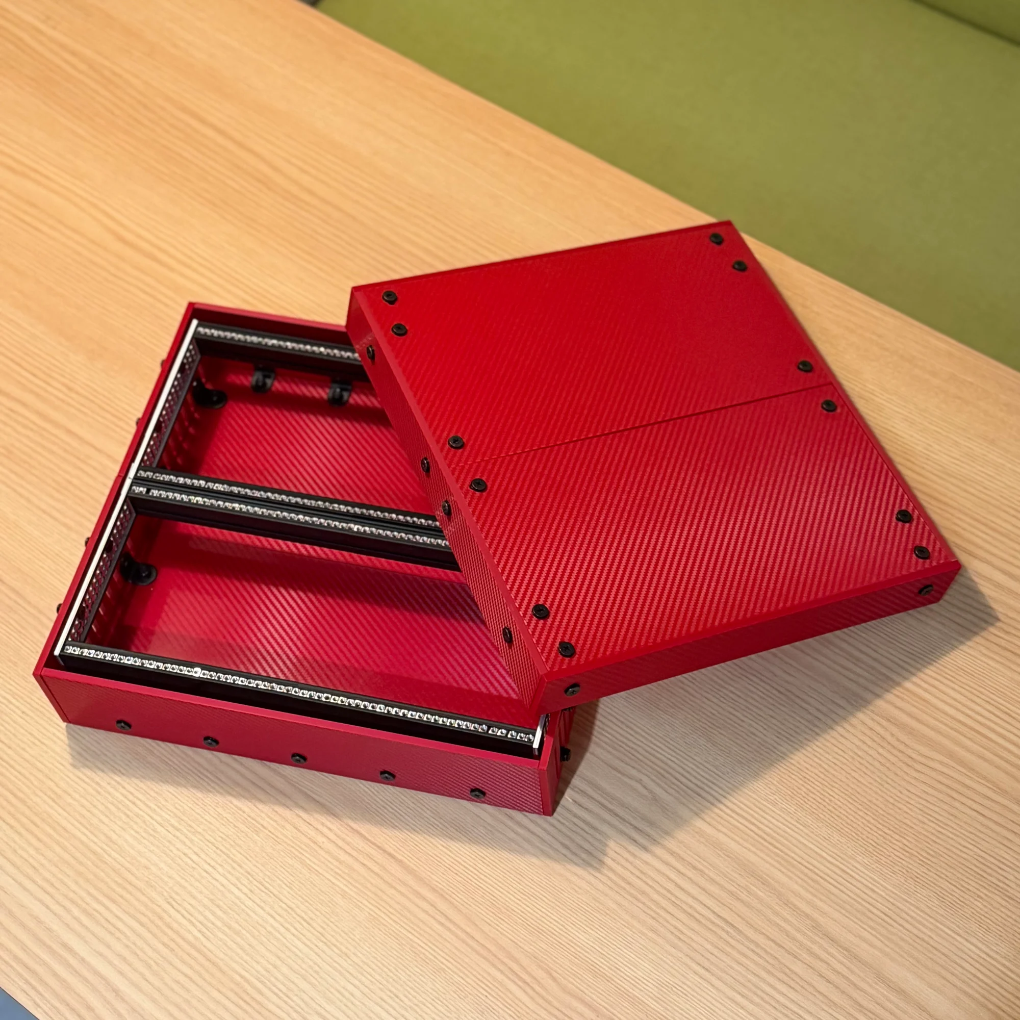
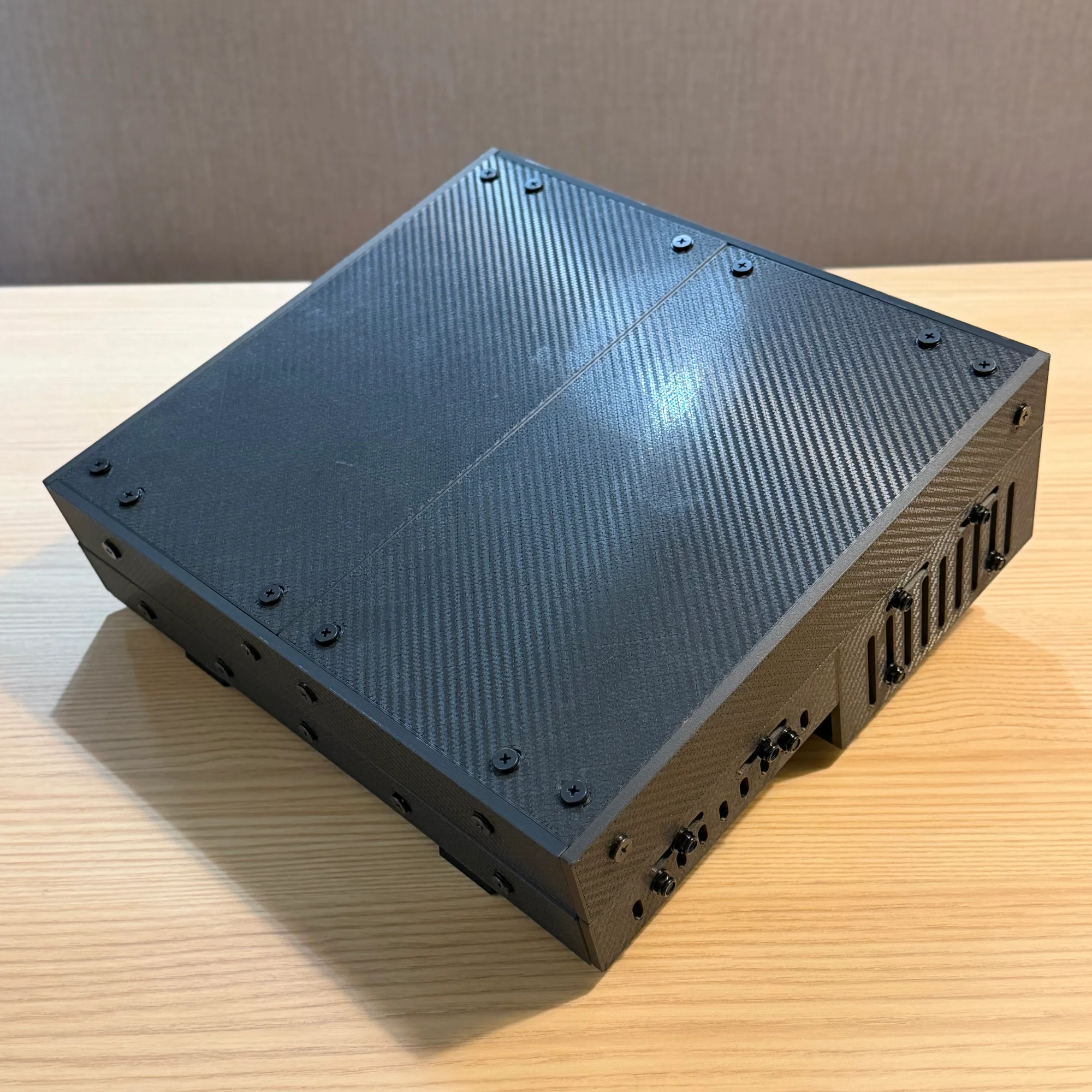
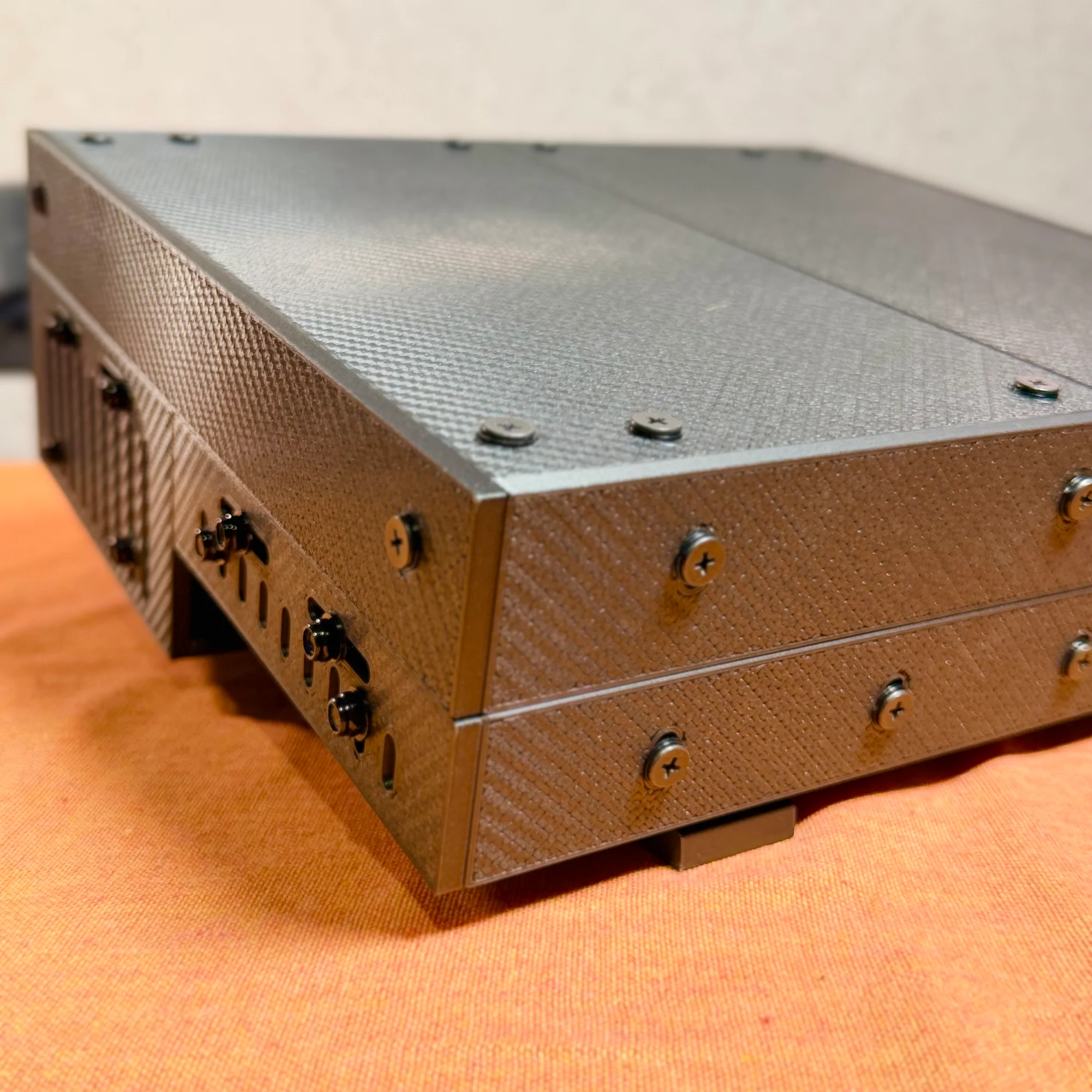
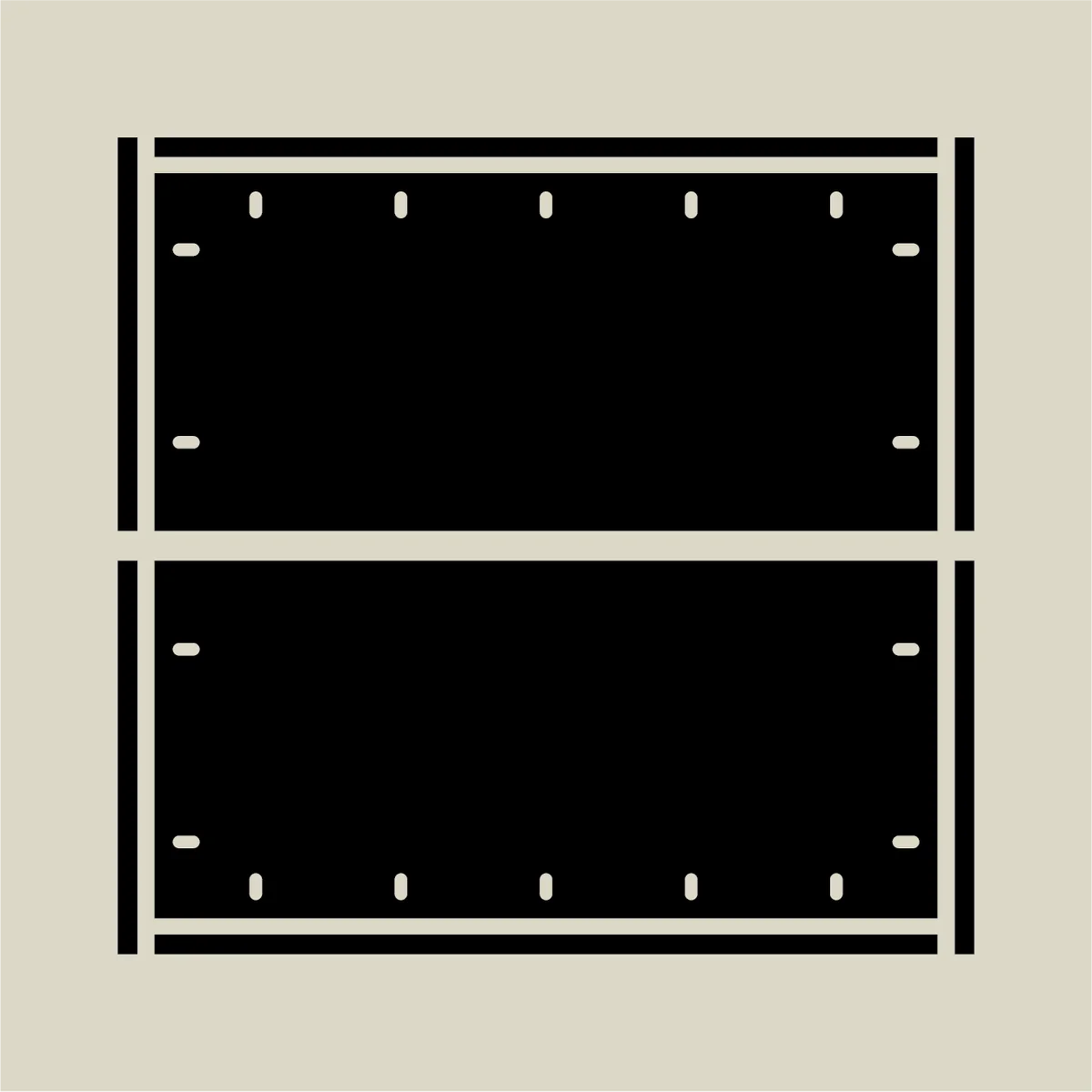
3. Base
The main body of the outer box is what we call the base. For the shallow version, the rear side is deeper and the front side is shallower. This stepped section is open, as shown in the photos below.

In the shallow version, this stepped section rests on the stand.
The deep version does not include a stand, but both the front and rear sides are equally deep.
This makes the deep version ideal when you need to accommodate many deep modules.
For the deep version, you can use a separate stand such as the zudo-stand to position the case at an angle.
4. Stand
As mentioned, the shallow version includes a stand that takes advantage of the height difference between the front and rear sides.
The stand is also 3D-printed, but unlike the main case, it does not use any metal brackets for assembly. The stand panels have interlocking notches that snap together, and the case body simply sits on top.
Assembly Steps
The following sections walk through the assembly process. The assembly is broken into five steps:
- Rail frame assembly
- Lid assembly
- Base assembly part 1: outer box
- Base assembly part 2: attaching the rails
- Stand assembly
The 10BOX has a different design from the previously developed zudo-block-40 and zudo-block-60, but the brackets, rails, screws, and nuts are the same. The general method of attaching panels and using fasteners is identical, so we recommend reading through the zudo-block assembly guide first for a smoother experience:
One additional note: the panels used in this case have a front side and a back side. You can assemble them in any orientation you prefer, but the product is designed so that placing the front side facing outward or on the visible side results in the cleanest finish. Please keep this in mind during assembly.
1. Rail Frame Assembly
Start with the rail frame. As mentioned, the rail frame uses the zudo-rail kit, and the assembly procedure is identical to the standard zudo-rail assembly instructions. Please refer to the following guide:
Since the zudo-rail comes in several variants, here is a key point: the 10BOX rail consists of two 3U 60HP rail frames joined together. When attaching the aluminum side frames to the rails, you need to insert the linking panel between them, as shown below.
For non-Metal materials, excessive force may cause breakage, so please read the assembly guide carefully before proceeding.
Note: For non-Metal versions, two 30HP rails are joined to make 60HP. The diagram above is simplified, so please be aware of this.
2. Lid Assembly
Once the rail frame is complete, assemble the lid. We do the lid before the base because it is simpler.
Both the lid and base use the same basic construction: panels are connected with L-brackets, screws, and nuts. So from here on, the process is essentially the same — combine panels and secure them with L-brackets using screws and nuts.
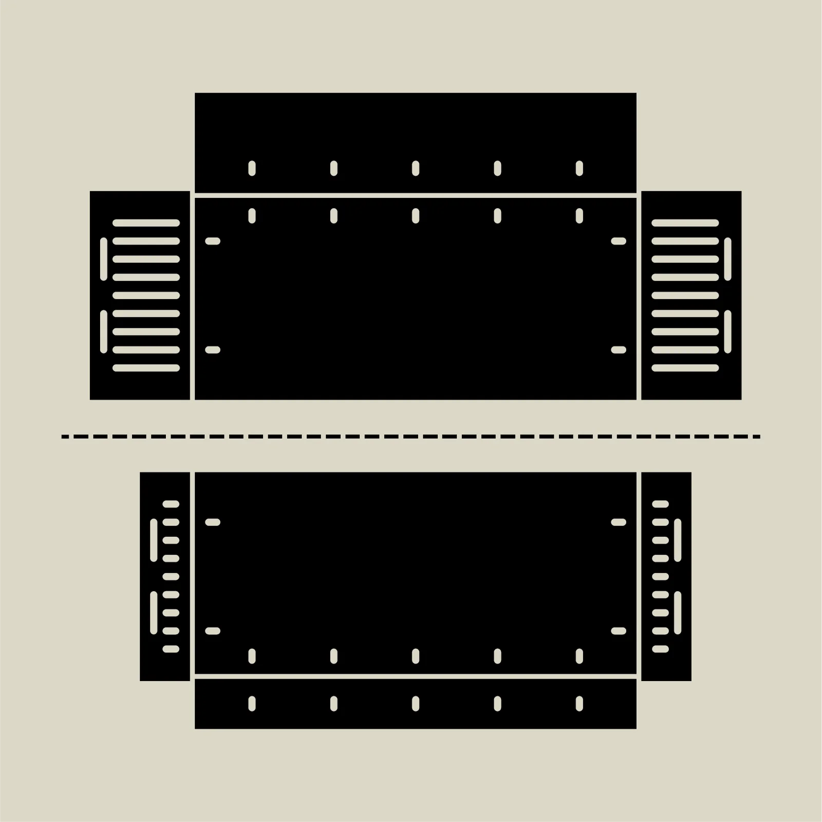
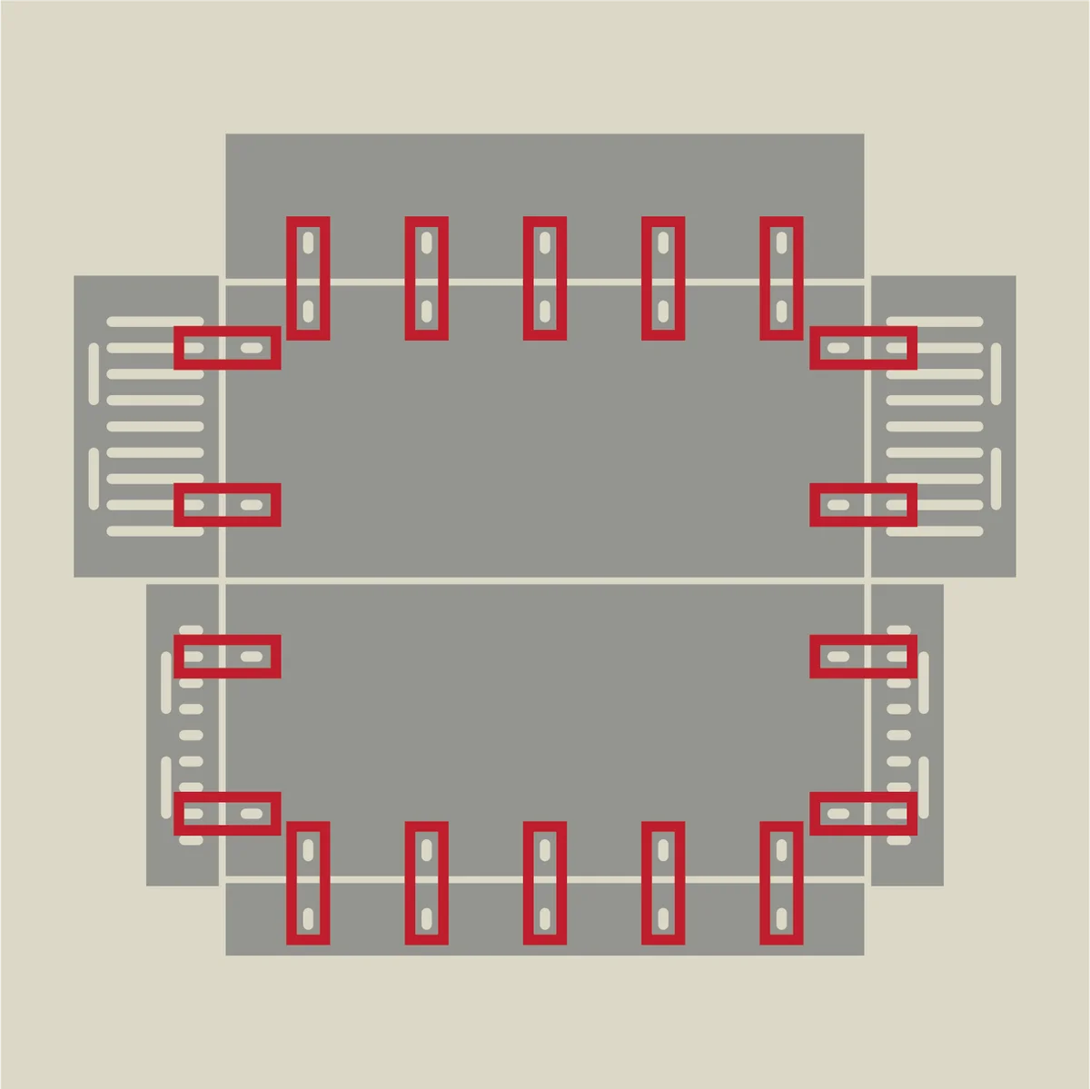
Below are the unfolded diagram and a diagram showing the L-bracket positions marked in red.
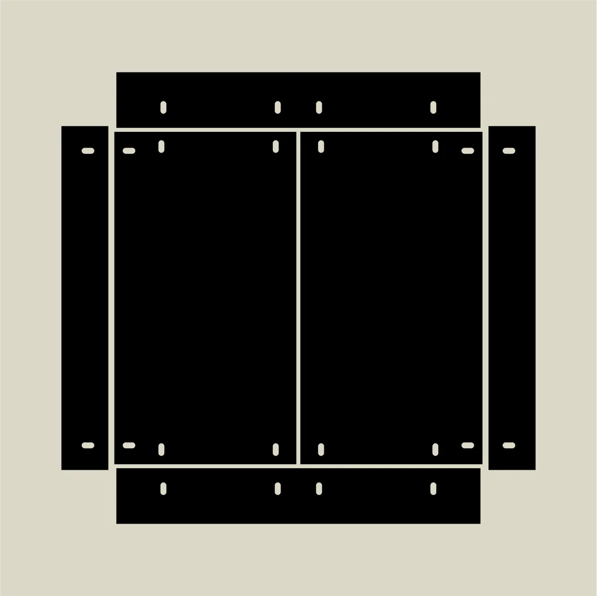
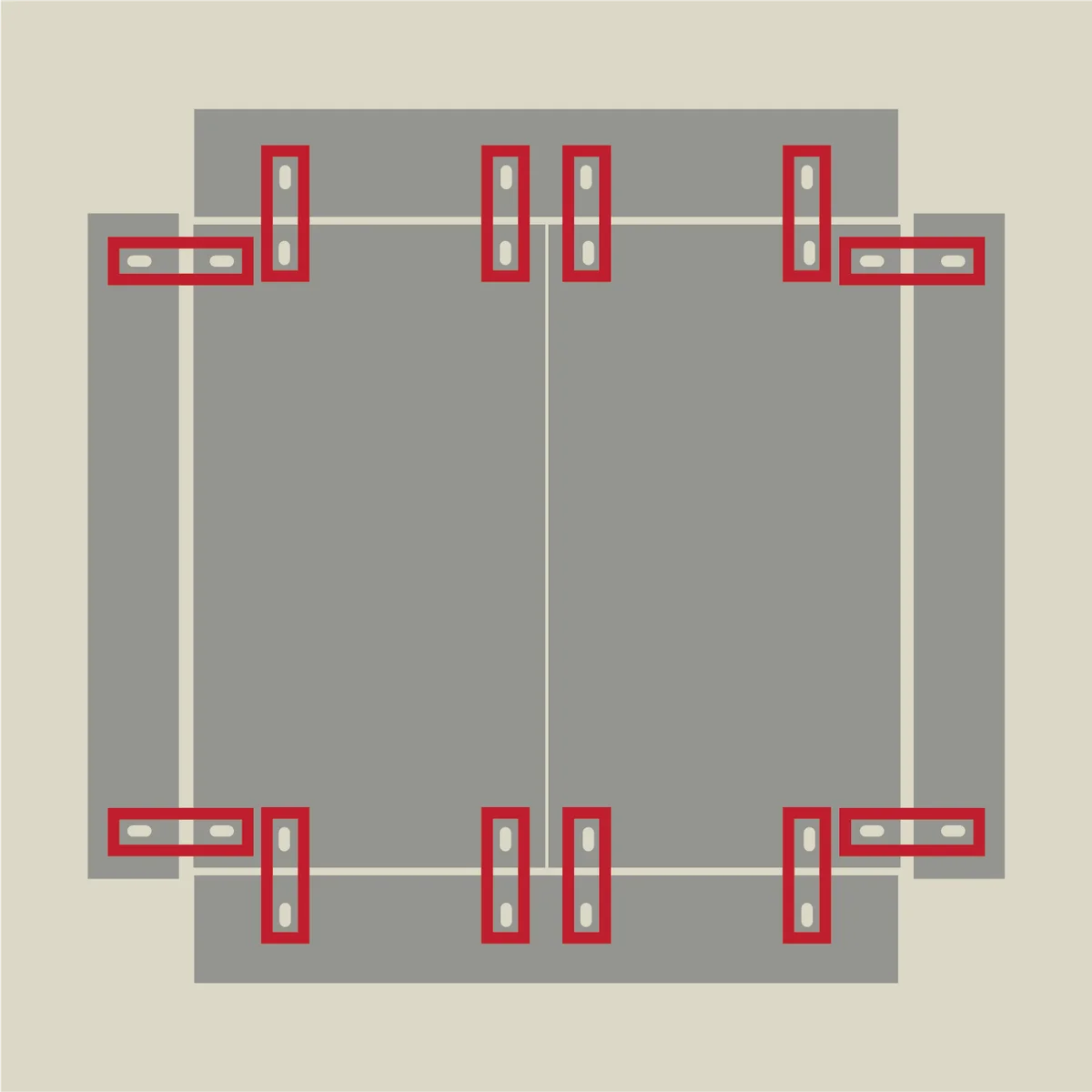
Secure the red-marked positions with L-brackets, screws, and nuts. The screws used for lid assembly are the 12mm shorter screws — the ones with the larger quantity in the kit.
Regarding panel alignment: the side panels of the lid extend beyond the top panel, and the front/rear panels match the combined width of the two top panels. This is a bit tricky to describe in words, so here is the unfolded diagram alongside an illustration showing the non-top panels standing upright.
When fully assembled, the top panels sit inside the surrounding front, rear, and side panels.
The screw holes are positioned so everything aligns naturally. Just follow the hole positions, but confirm that the four corners come together as shown in the diagrams, then secure with L-brackets.
Key points for lid assembly:
- Hold the panel joints straight by hand while tightening the nuts
- Position screw heads on the outside and nuts on the inside
- Orient the front/rear panels with the stepped edge facing inward
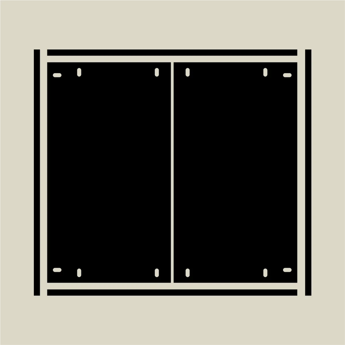
Please see the following photos.
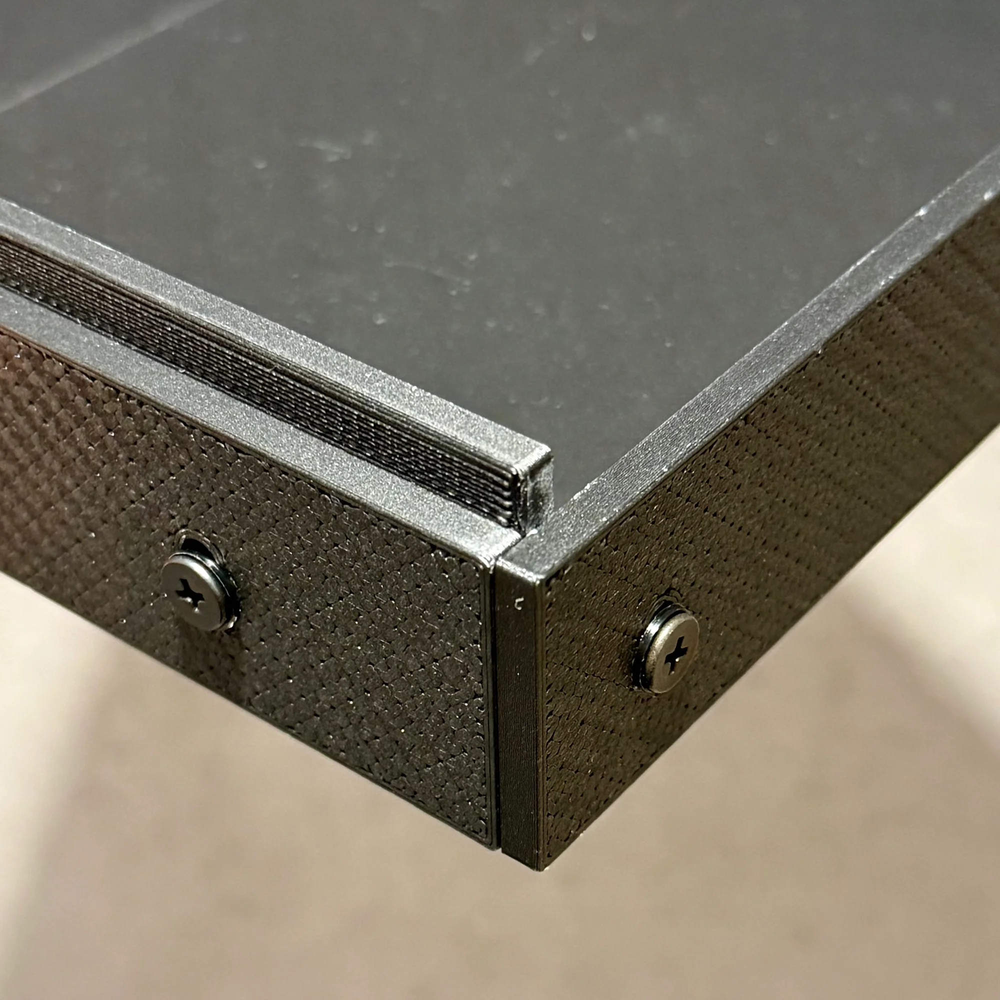
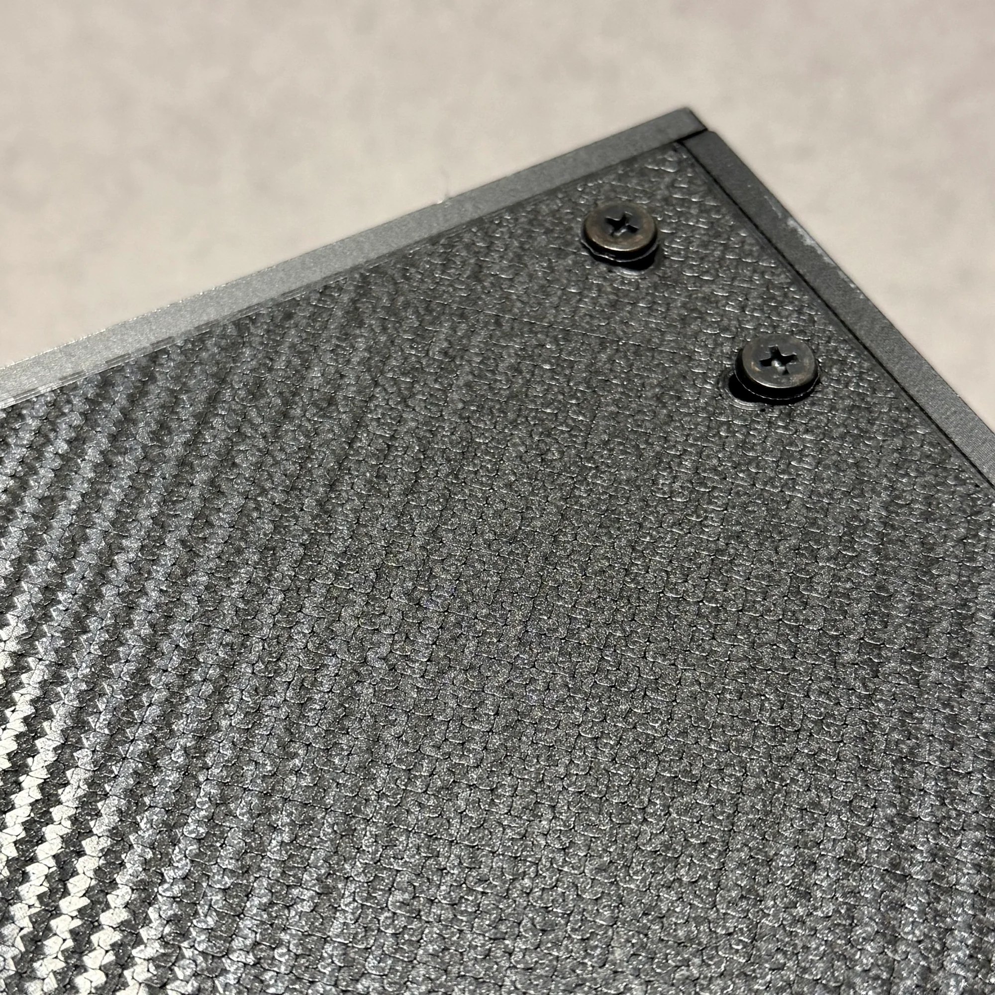
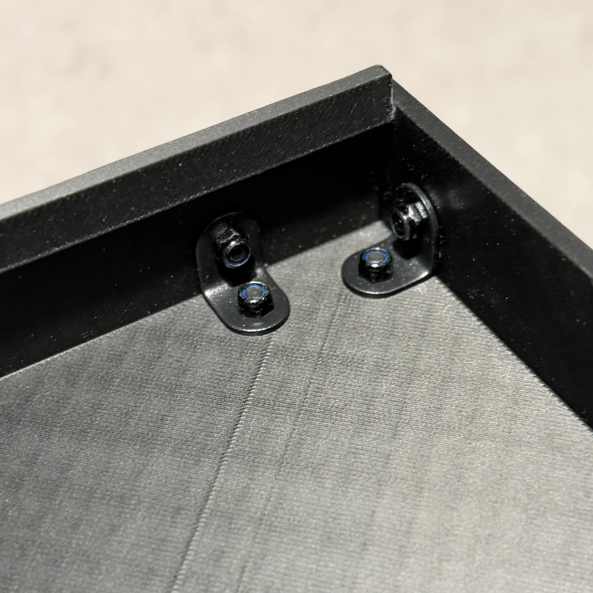
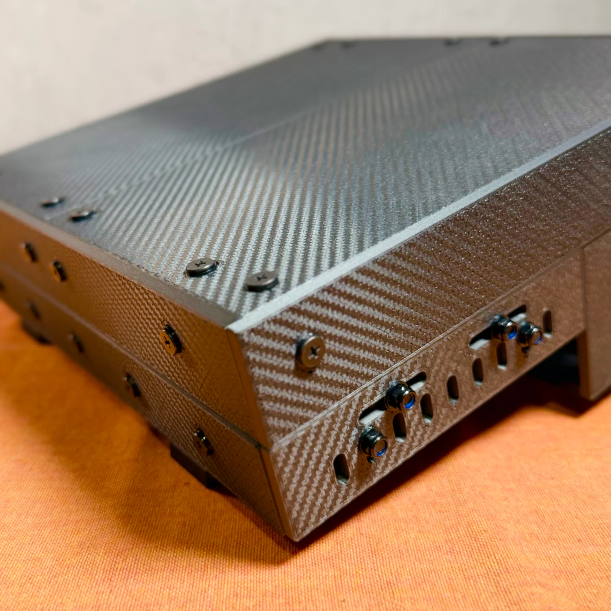
The first photo shows the top of the lid; the second shows the inside. You can see screw heads on the outside and nuts on the inside. In the first photo, you can also confirm at the far edge that the panels meet flush without any unevenness.
Specifically: insert screws from outside through to the inside, and attach nuts on the inside of the panel. The screw holes in these panels are oval-shaped, not perfectly round. This allows you to adjust the alignment so that the panel joints at the four corners are flush and even. Hold them in place by hand while tightening the nuts.
When tightening screws, place the included 1mm washer under the screw head. So from outside to inside, the order of hardware is:
- Screw head
- 1mm washer
- Panel
- L-bracket
- Nut
The screw holes work from either side, but since nuts have some height to them, placing the nuts on the inside produces a cleaner exterior finish.
Also, the front and rear panels are the only ones with a stepped edge. Make sure this stepped portion faces inward during assembly.
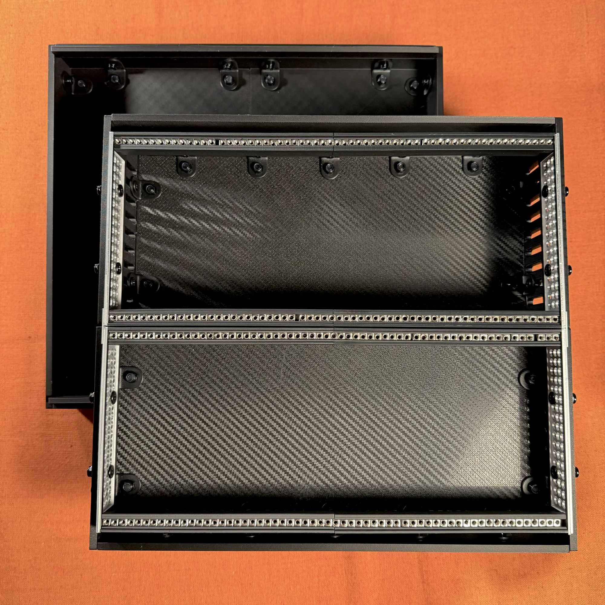
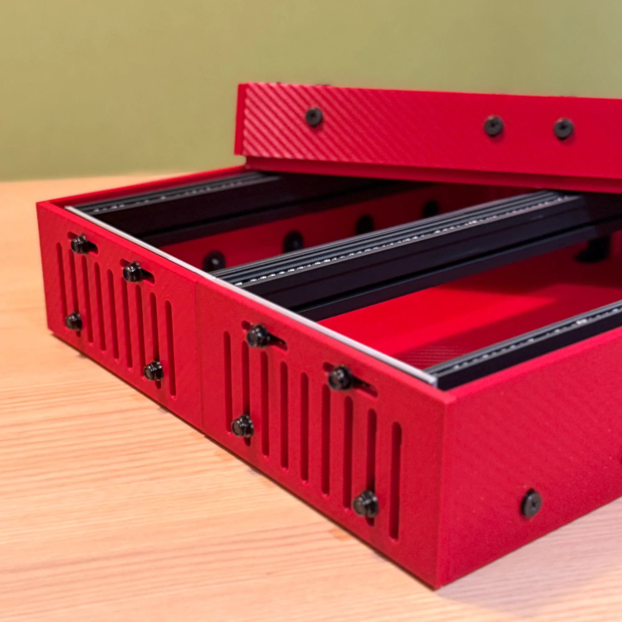
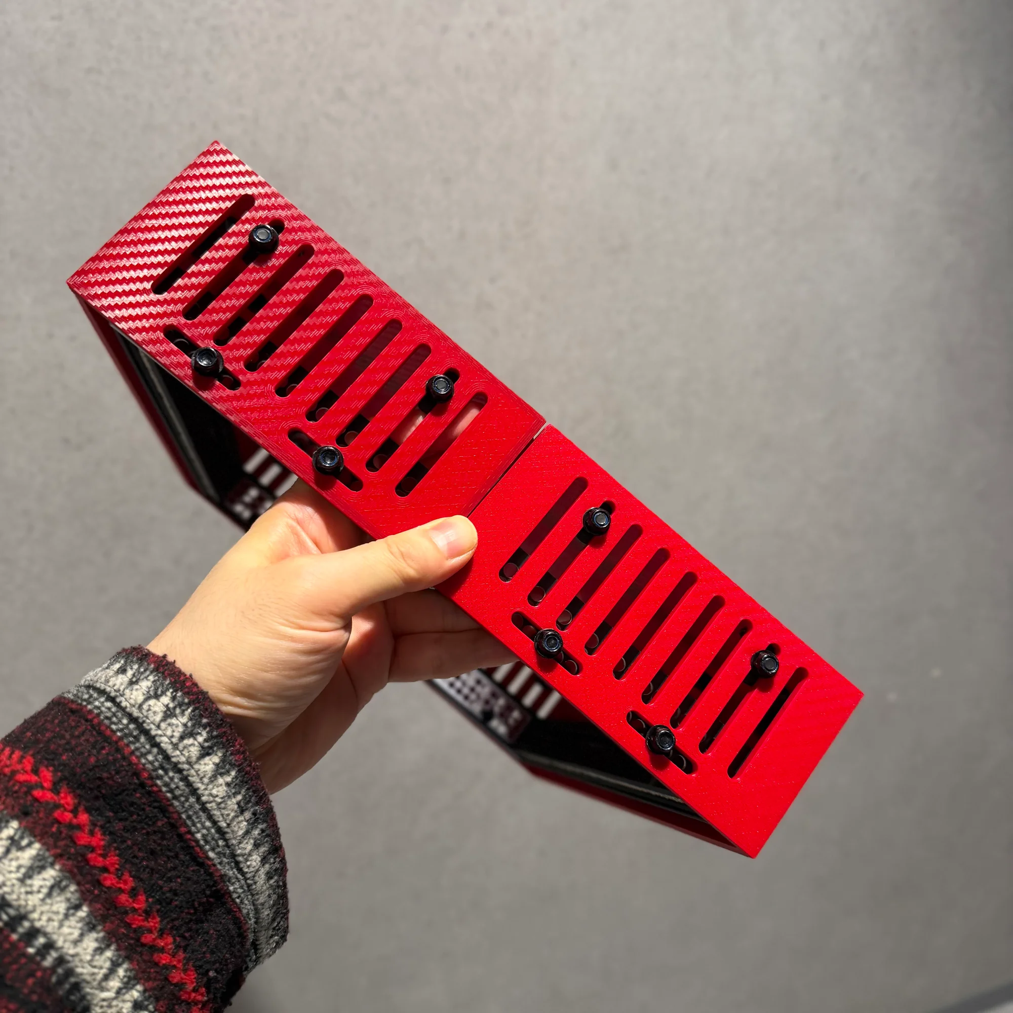
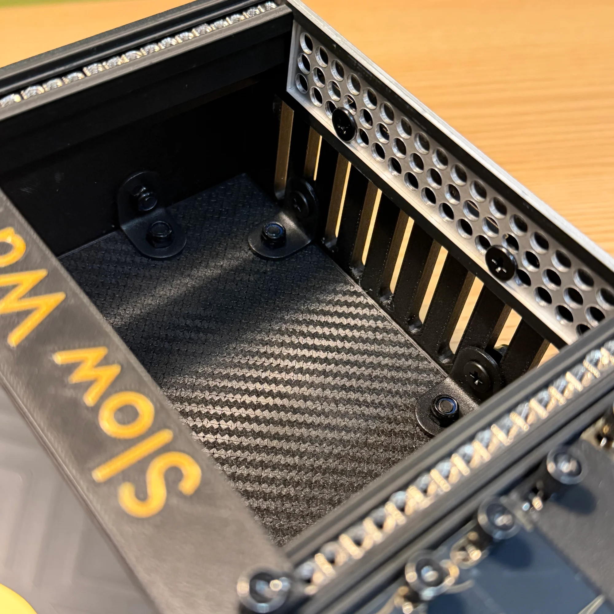
3. Base Assembly Part 1: Outer Box
Next, assemble the base.
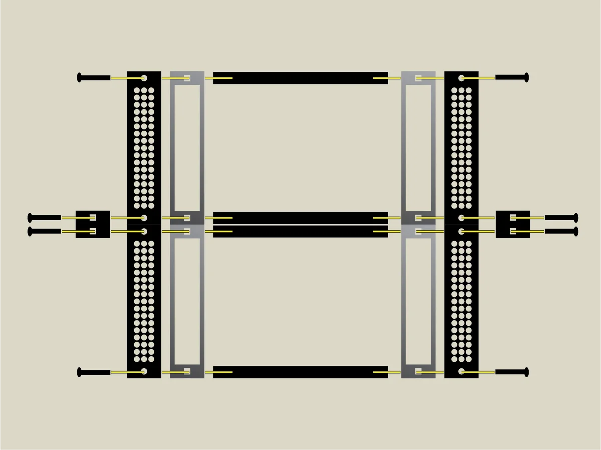
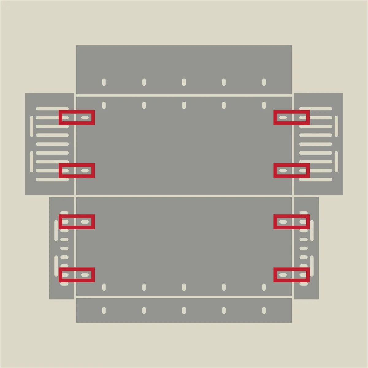
Think of the base as two separate halves: the rear section and the front section. Below is the unfolded diagram for the shallow version, split into rear and front.
The assembly procedure is fundamentally the same as the lid. The red outlines below indicate L-bracket positions. Unlike the lid, the side panels of the base section have many tall, narrow holes for screws. The side panels should be oriented with the wider horizontal holes at the top. Be careful not to install them upside down.
The assembly is basically the same as the lid, with one important difference: the fastening order for the side panel to bottom panel connection. Up to this point, the screw-and-nut fastening order has been: from the outside…
- Screw head
- 1mm washer
- Panel
- L-bracket
- Nut
However, at the following connection points — only where the side panels attach to the bottom — a different order is required.
For these locations, fasten from the inside in this order:
- Screw head
- L-bracket
- Panel
- 1mm washer
- Nut
This applies only to the side panel attachment points, shown in the red outlines in the photo below.

The key difference is that the nut is placed on the outside. The 1mm washer also goes on the outside. For reference, the blue-outlined section in the photo shows the standard fastening method with the nut on the inside.
The reason for this reversed fastening is to prevent the nuts from interfering with the rail frame when it is attached later. Because the front section of the base is shallow in the shallow version, having the nuts on the inside would prevent the rail frame from fitting properly. Please be careful — forcing the rail frame in could cause it to break.
For the deep version, both the front and rear sections are equally deep. Follow the same procedure for assembly.
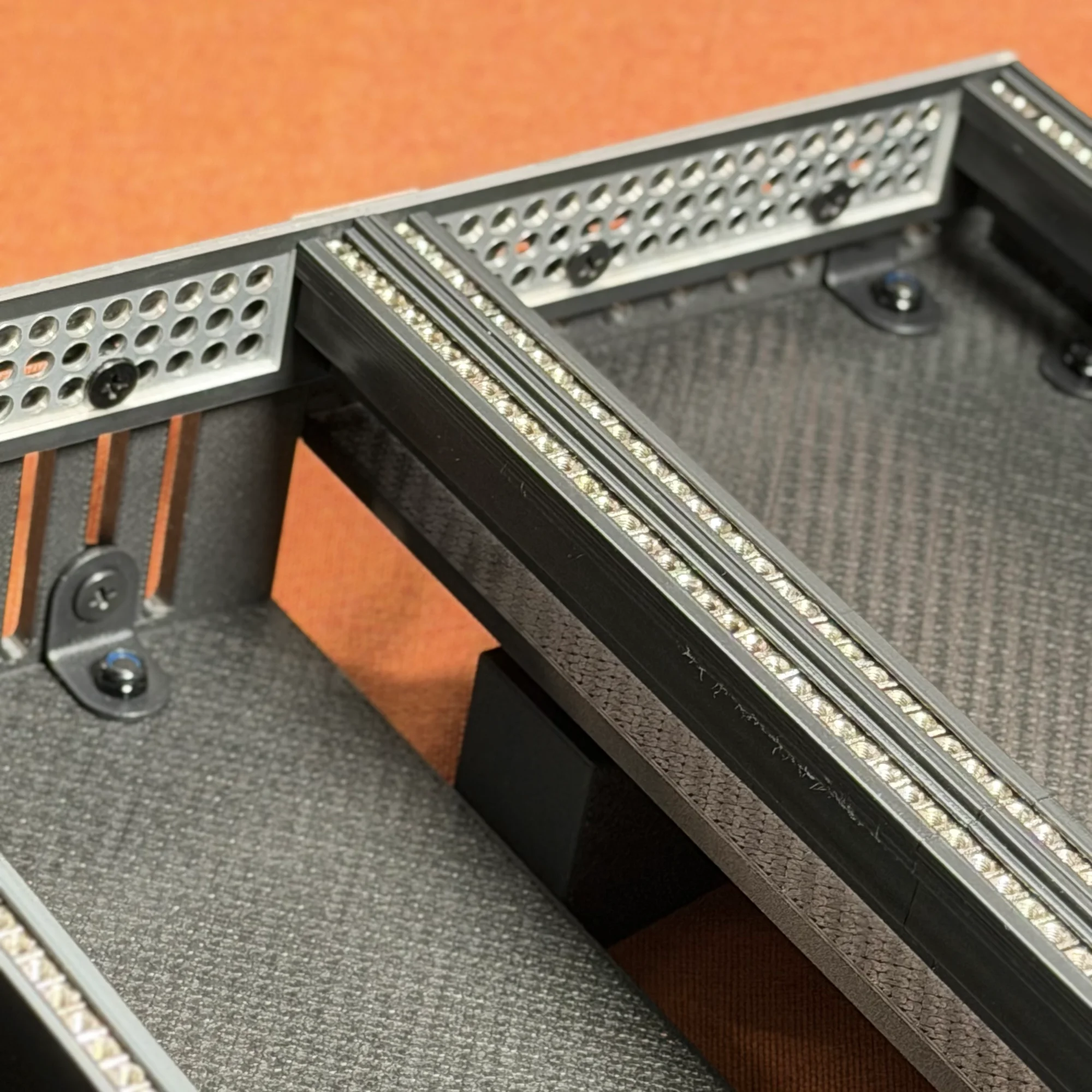
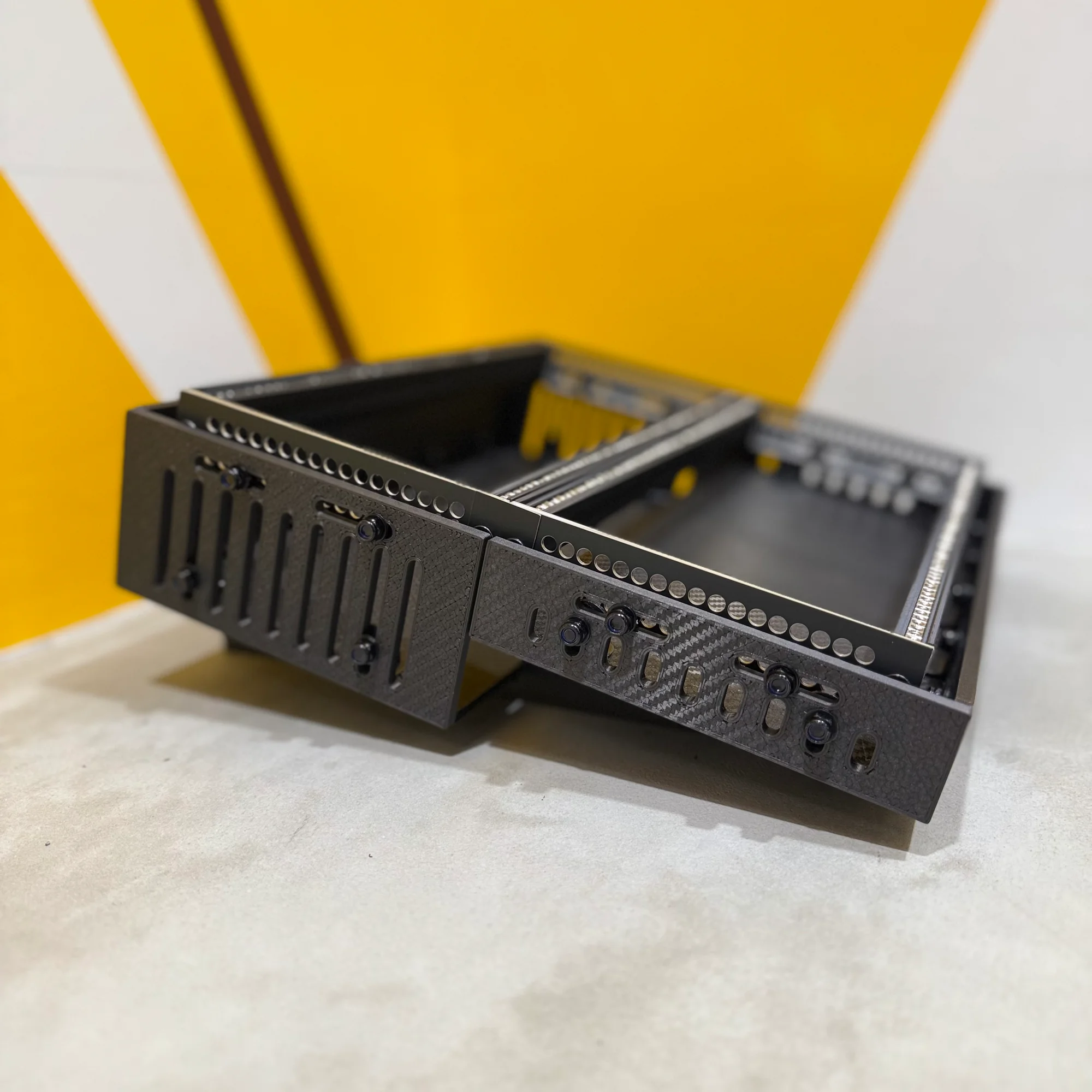
4. Base Assembly Part 2: Attaching the Rails
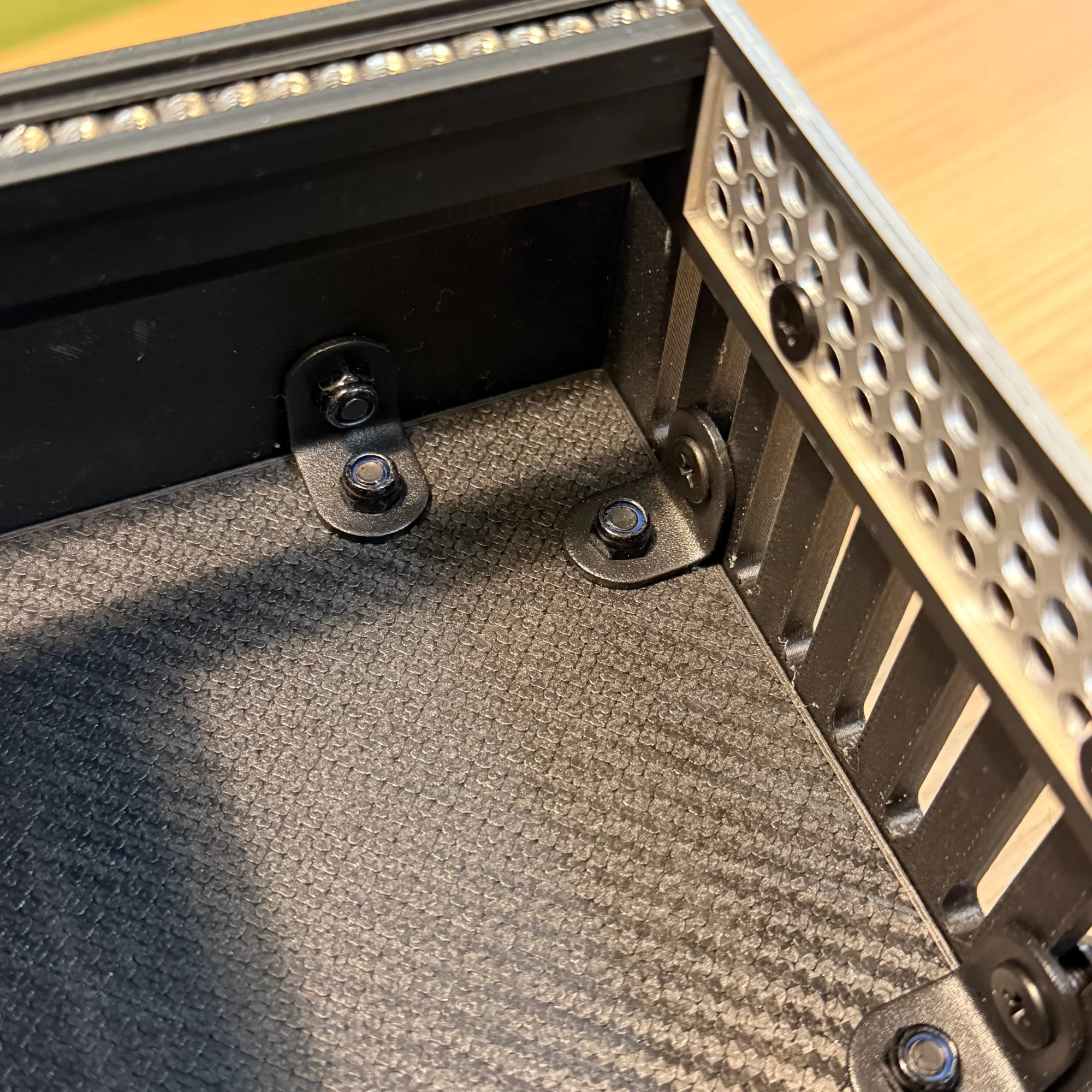
Once the two halves of the base are assembled, attach the rail frame.
The two base halves are not directly connected to each other. Instead, the rail frame bridges between them. Align the holes in the rail’s aluminum side frames with the horizontal holes at the top of the side panels, and secure with screws and nuts.
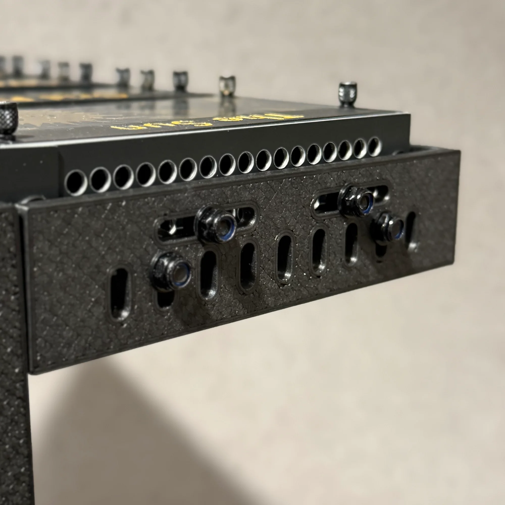
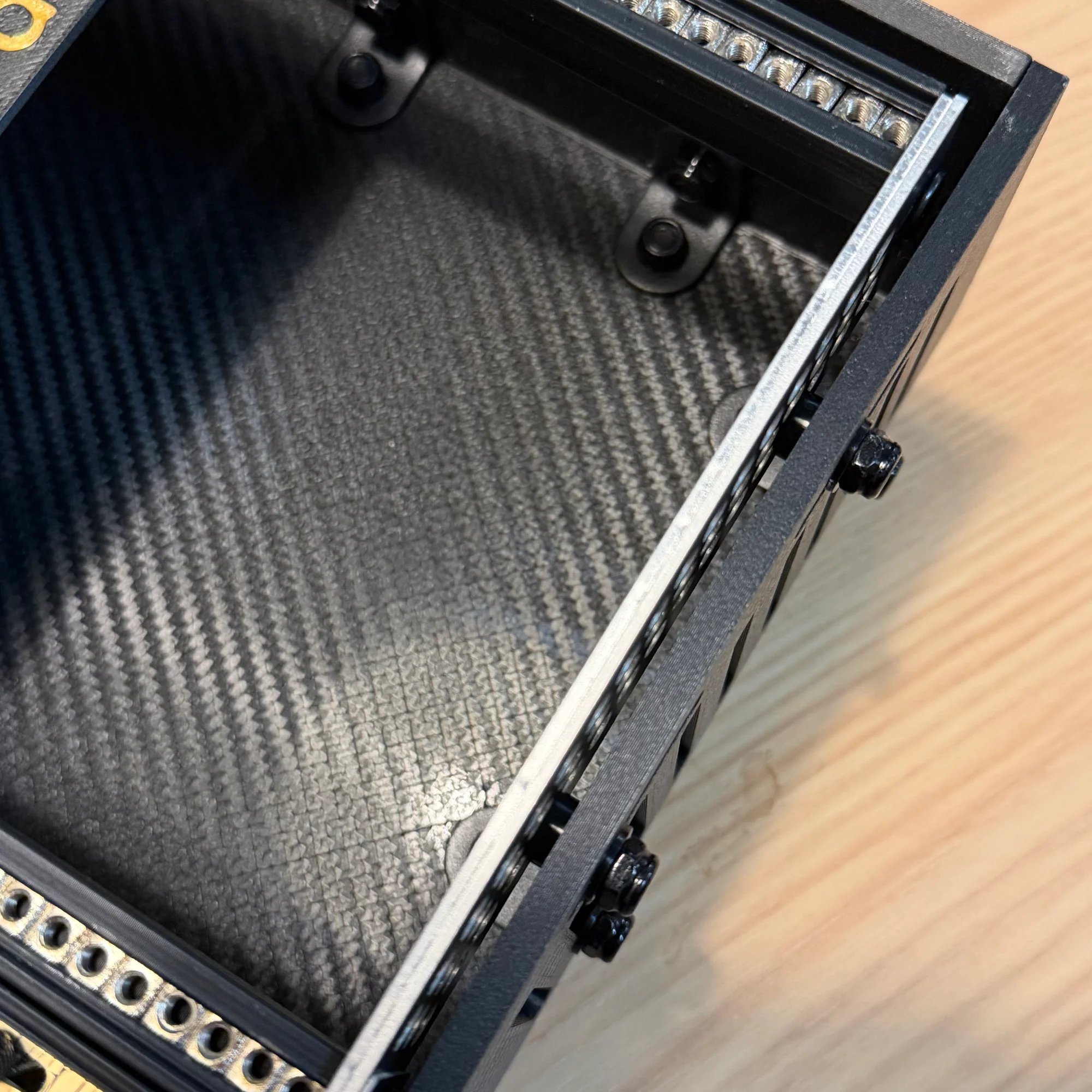
As in the previous step, pay attention to the fastening order. Fasten from the inside in this order:
- Screw head
- Rail aluminum frame
- 3mm washer
- Panel
- 1mm washer
- Nut
The 3mm washer fills the gap between the rail’s aluminum side frame and the outer box’s side panel. In the photos above, you can see the washer sandwiched between the panel and the aluminum frame.
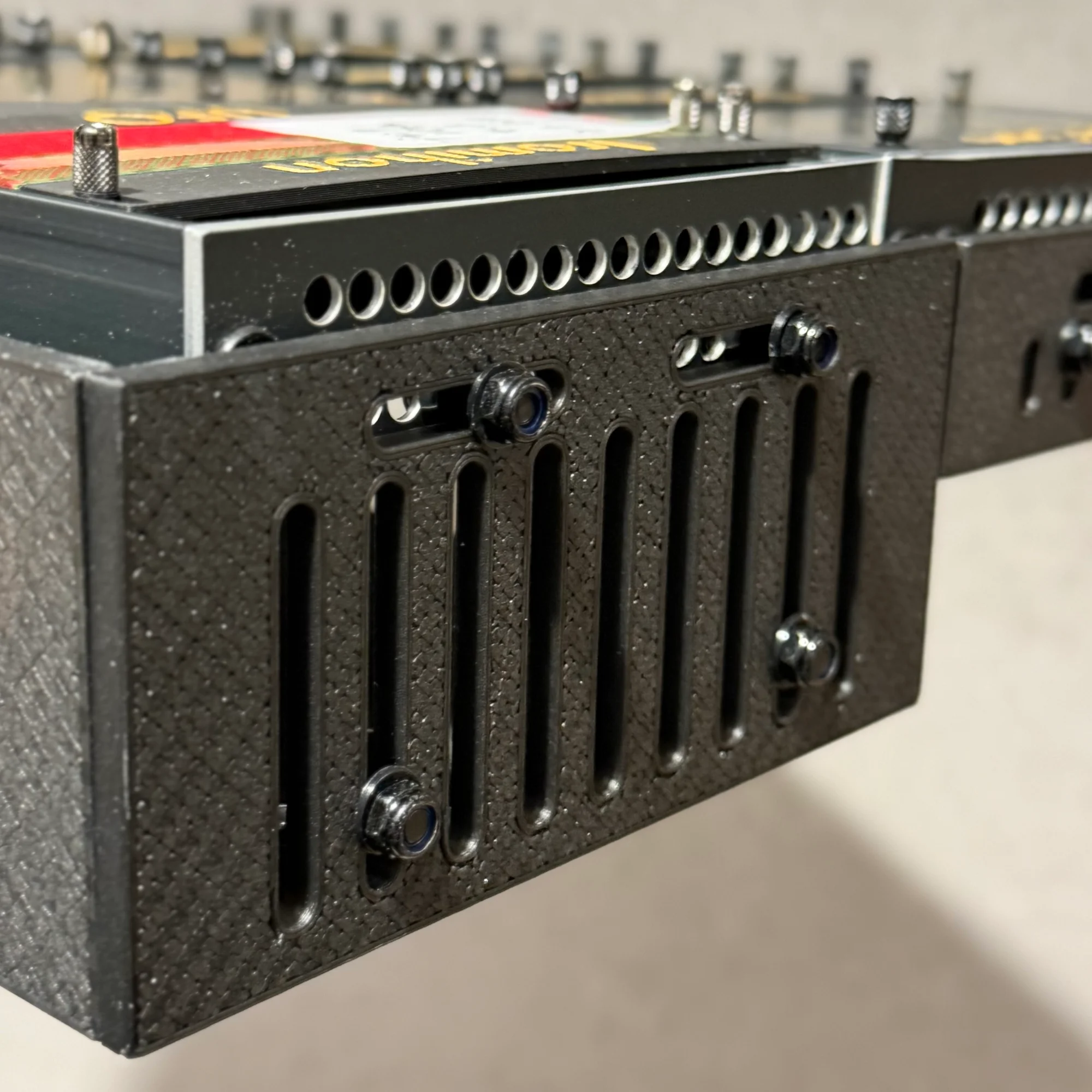
Rail Mounting Position
The rail mounting position differs between the shallow and deep versions. Please see the following diagrams.
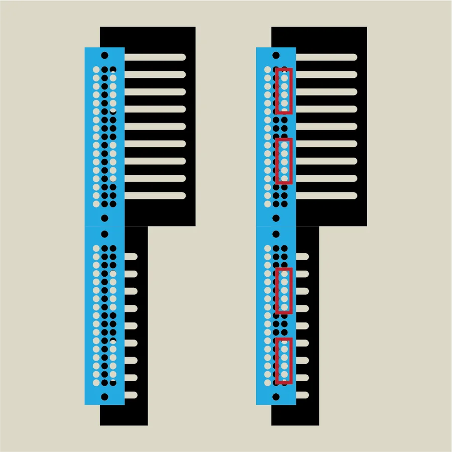
The first diagram shows the mounting position for the shallow version. The rail’s aluminum side frames have many holes arranged in three rows. For the shallow version, the front box section is shallow, so you must use the bottom row of holes to attach the side panels. In other words, the shallow version has no depth adjustment.
The second diagram shows the mounting position for the deep version. Since both the front and rear sections are deep, the rail frame can be mounted at any of the three rows, giving you a choice of three depth levels. Using the bottom row like the shallow version allows deeper modules to fit. Using a higher row positions the rails deeper within the case.
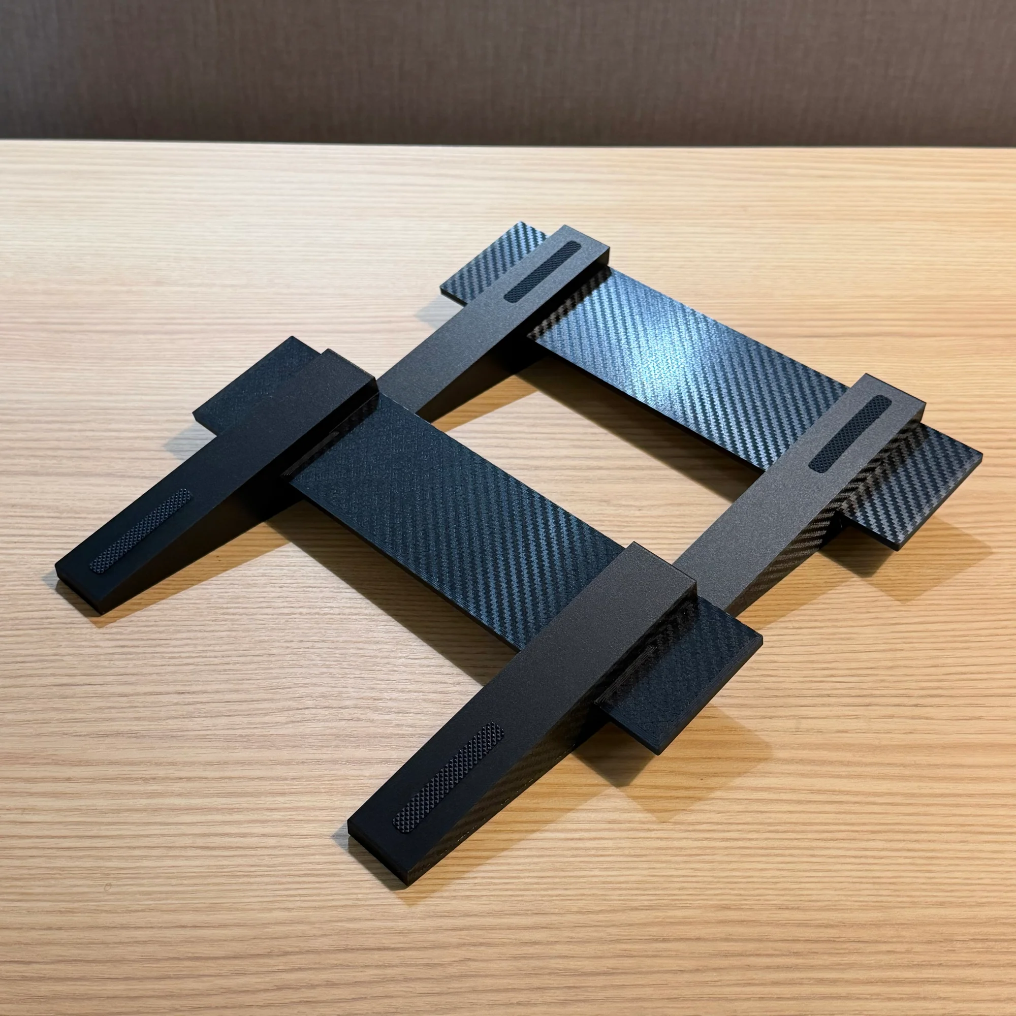
5. Stand Assembly
Finally, assemble the stand. The stand is included only with the shallow version.
The stand consists of two leg pieces and two connecting pieces. Snap the connecting pieces into the notches on the leg pieces to assemble the stand.
Rubber feet are included with the stand. Attach them to the bottom of the legs or the surface where the case rests, as needed for your use case.
That concludes the 10BOX JuBako assembly guide.
If you have any questions, please do not hesitate to contact us.