
This guide explains how to assemble the zudo-block-40 and zudo-block-60. The 40HP and 60HP versions differ only in width — the assembly procedure is exactly the same.
For product details, please refer to the following product pages:
- Required Tools
- Assembly Video
- Step 1: Rail Connection (60HP Lite/Dual Rail Version Only)
- Step 2: Frame Assembly
- Step 3: Box Assembly
- Step 4: Frame Mounting
- Assembly Tips
- Adjustable Angle Design
Required Tools
The following tools are needed for assembly. Please have them ready beforehand.
- Hex wrench (e.g., Amazon: Hex Wrench 9-Piece Set)
- Wrench (e.g., Amazon: Mini Wrench Set)
- Phillips screwdriver (e.g., Amazon: Screwdriver Set)
- Pliers (if available) (e.g., Amazon: Pliers Set)
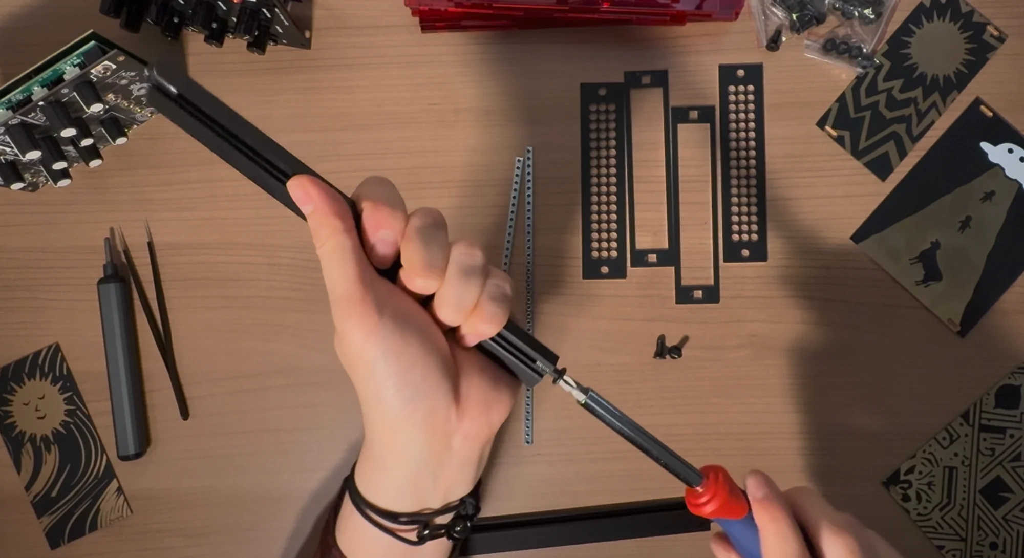
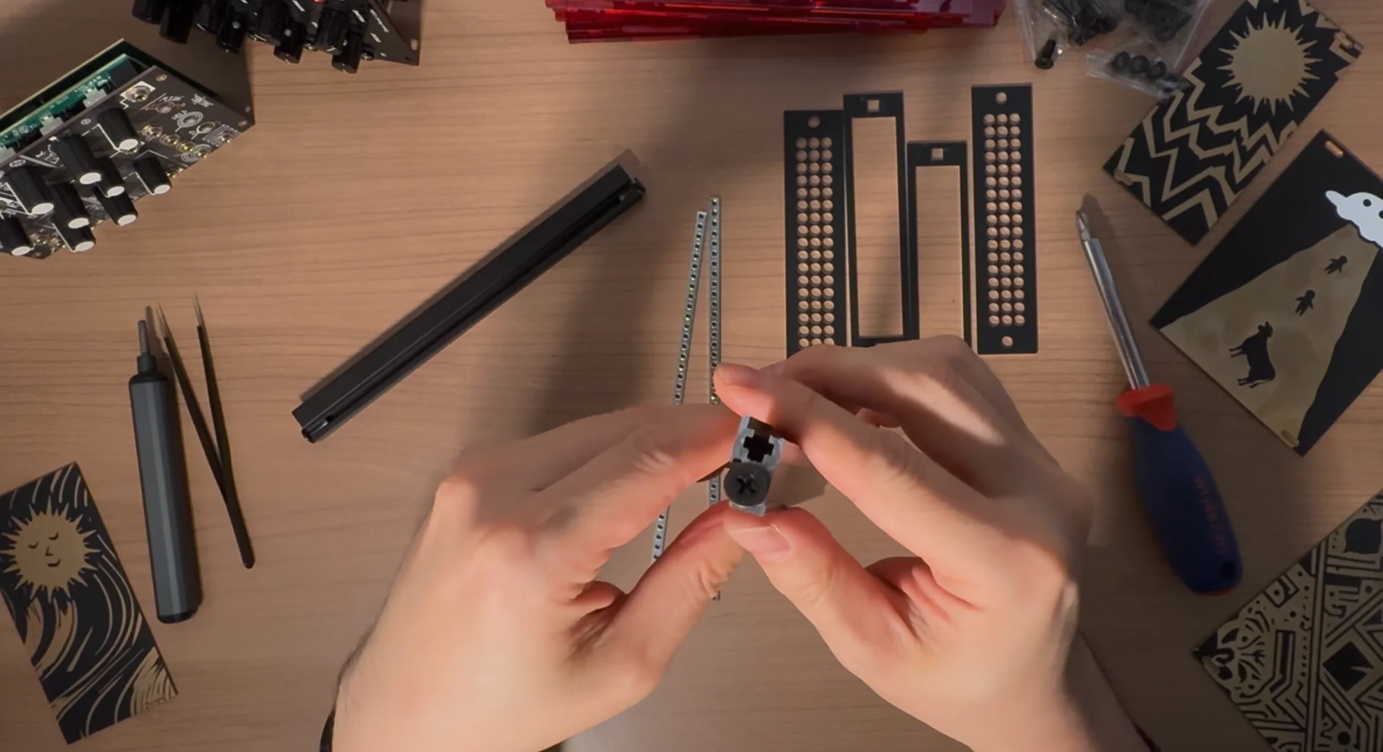
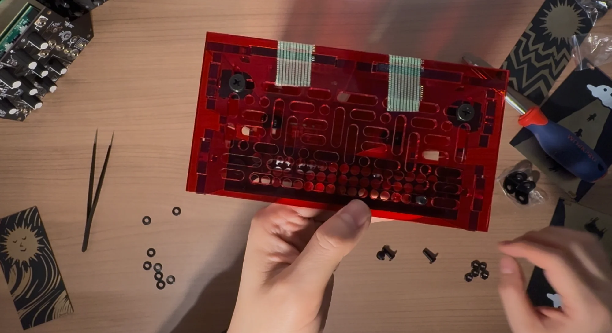
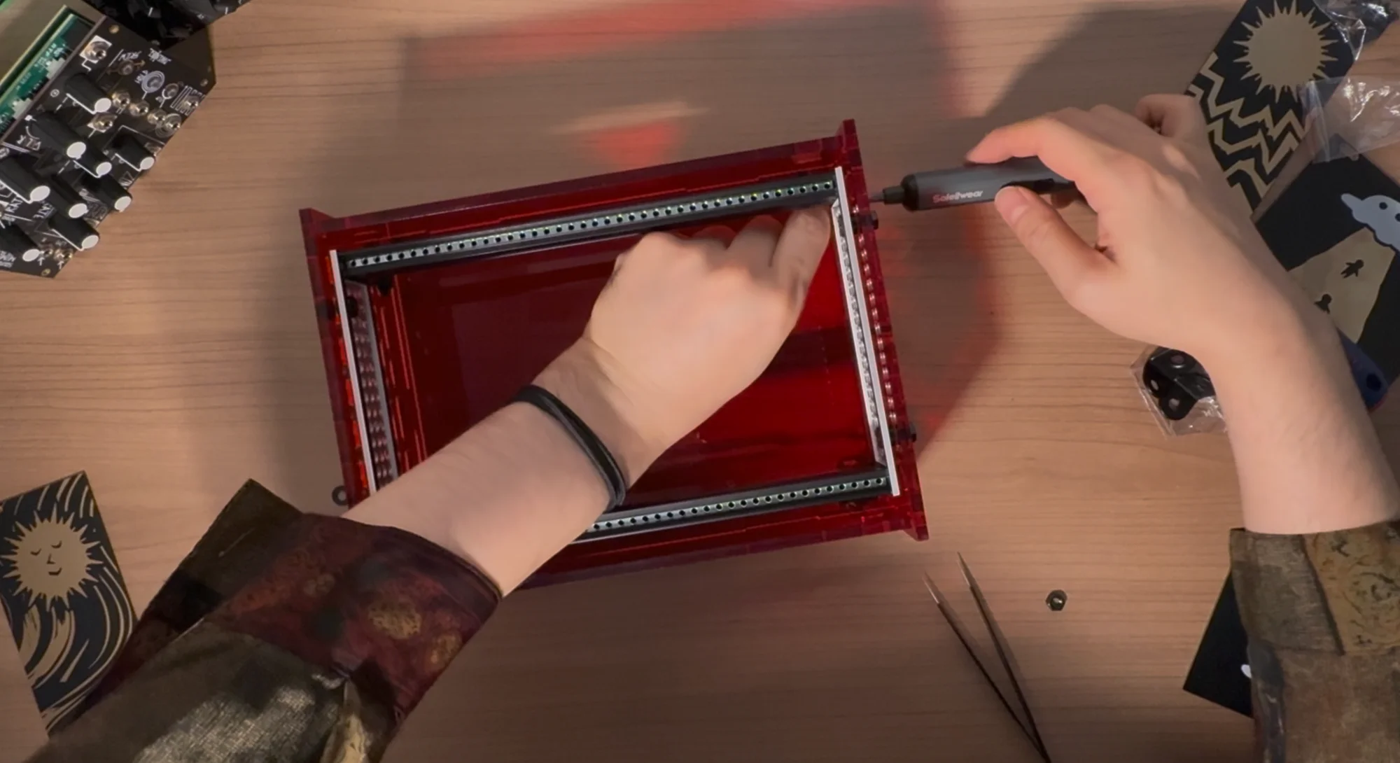
Assembly Video
First, here is an assembly video for the zudo-block-40. Since the zudo-block-60 follows essentially the same assembly procedure, please use this as a reference.
Step 1: Rail Connection (60HP Lite/Dual Rail Version Only)
If you are using Lite/Dual rails with the 60HP version, you first need to connect two 30HP rails to create a 60HP rail. For detailed instructions, please refer to the zudo-rail Assembly Guide.
This step is not required for the 40HP version or Metal rails.
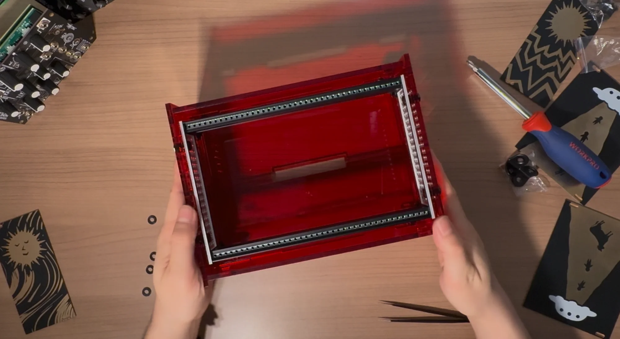
Step 2: Frame Assembly
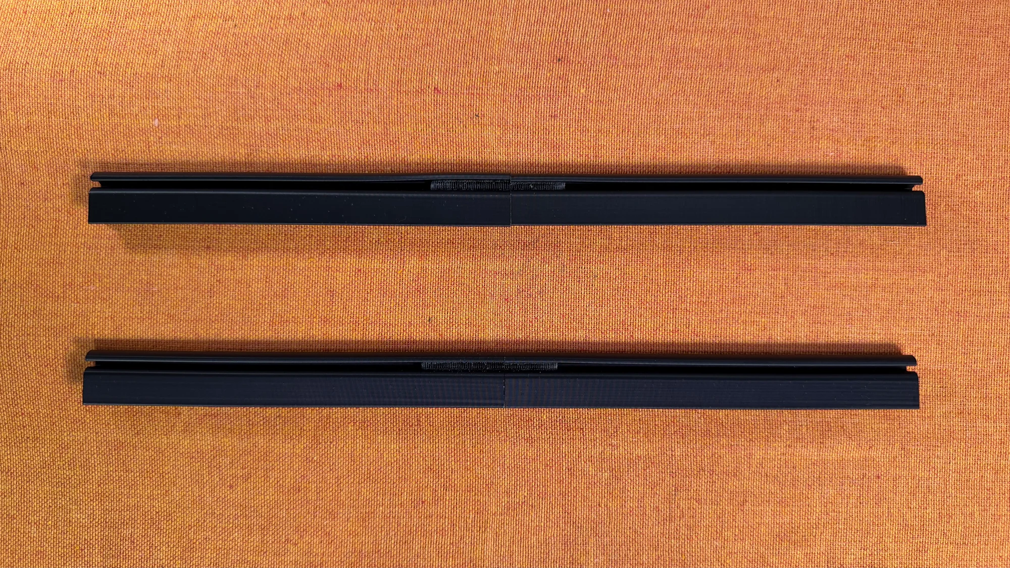
- For Metal rails, screw M5 12mm screws (the slightly shorter ones) into the bumpy area on the side of the rail where no bar nuts pass through. Since the rail has no pre-made threads, this step creates the threads by driving in the M5 screw first.
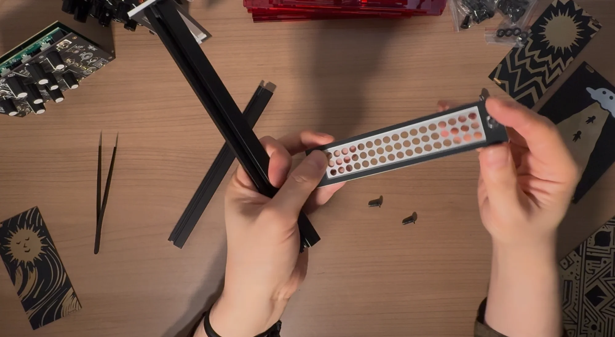
- Remove those screws, then assemble by sandwiching the two rails between the rail mounting panels. These rail mounting panels come as a set of two: one with large rectangular holes and one with many circular holes. Assemble them so that the panel with rectangular holes faces inward.
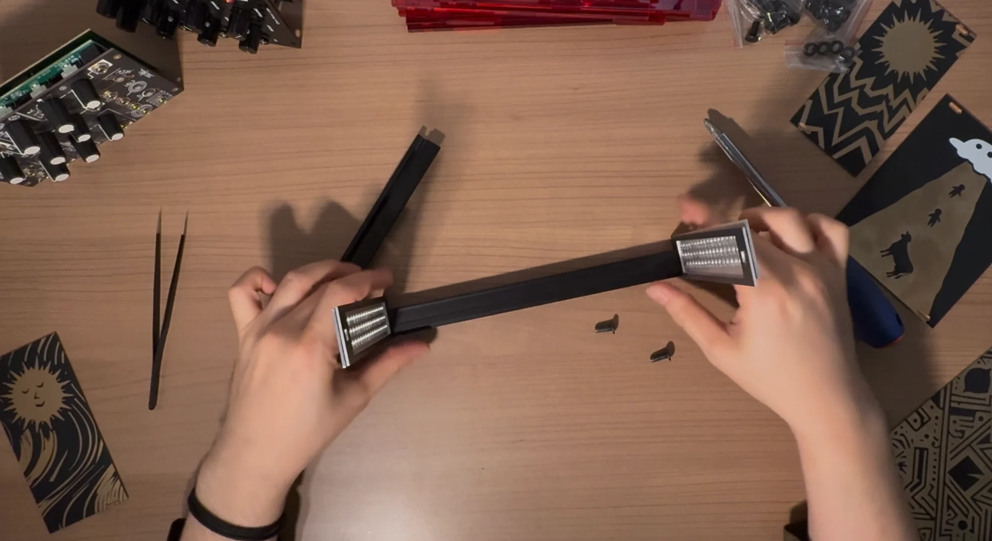
- The rails have a lip/edge. Make sure the lip faces outward.
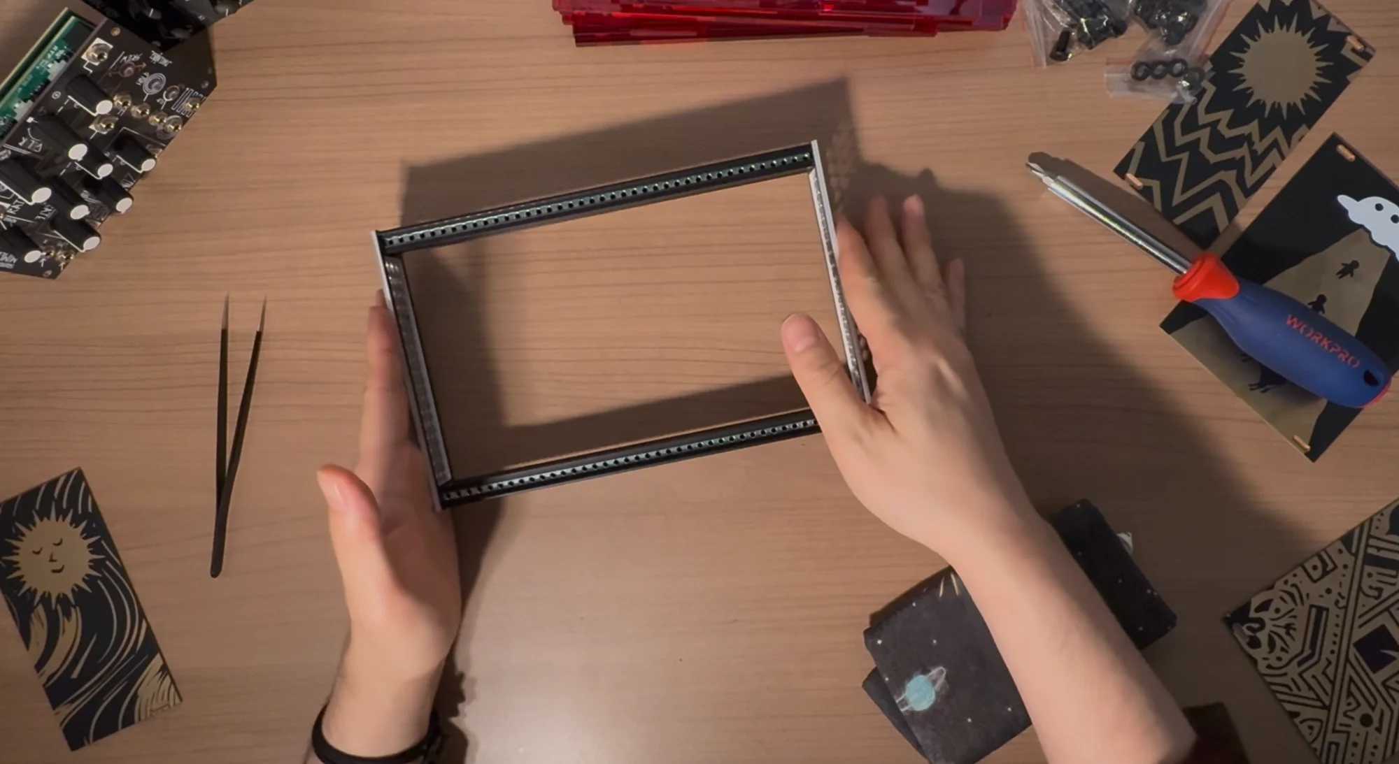
- Secure the rail mounting panels and rails with M5 screws (12mm for Metal / 40mm long screws for all others). Start by loosely tightening the screws, then insert a module between the rails to test the fit, confirming the rails are not tilted at an angle, and then tighten the screws firmly.
- Remove the module you used for testing. The frame section is now complete.
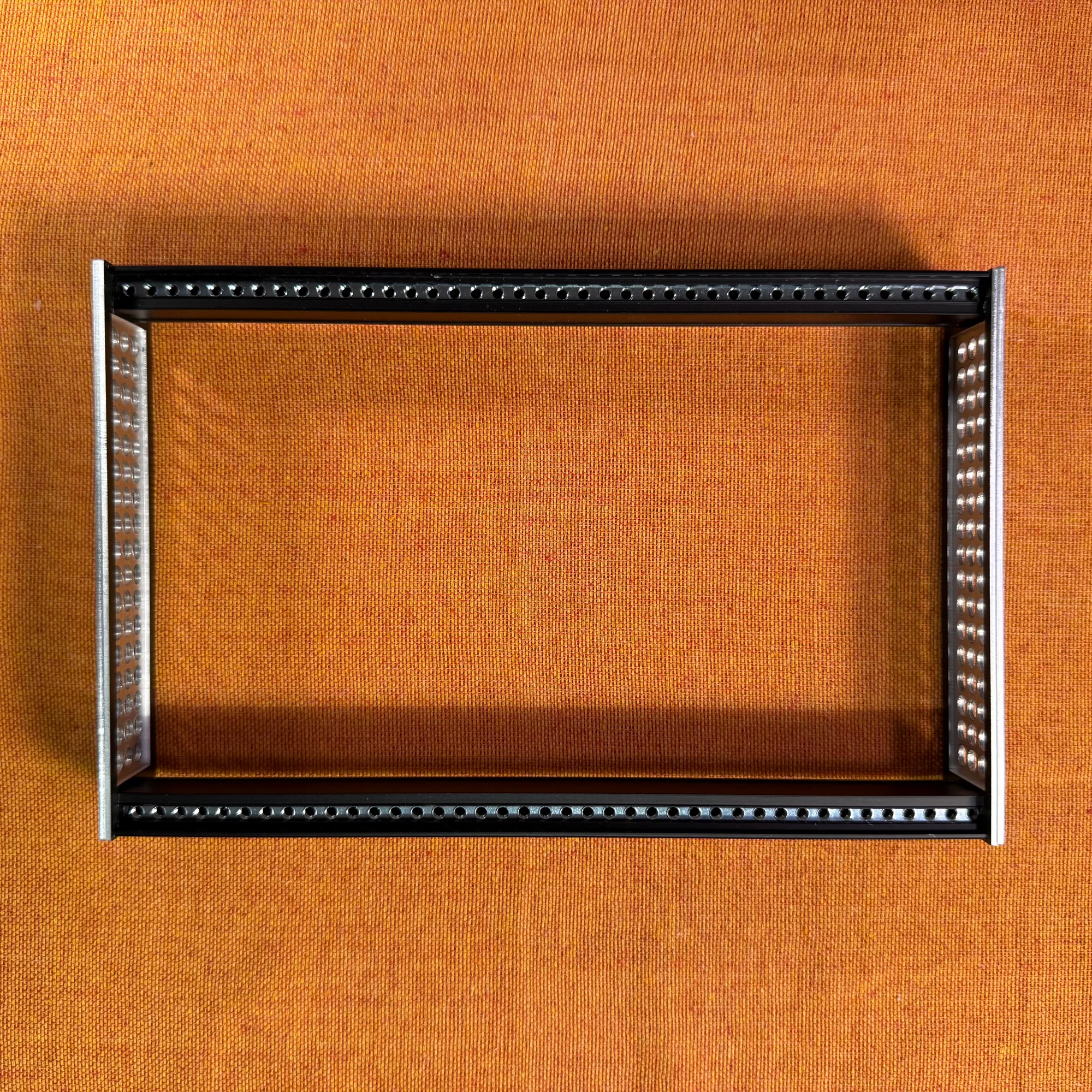
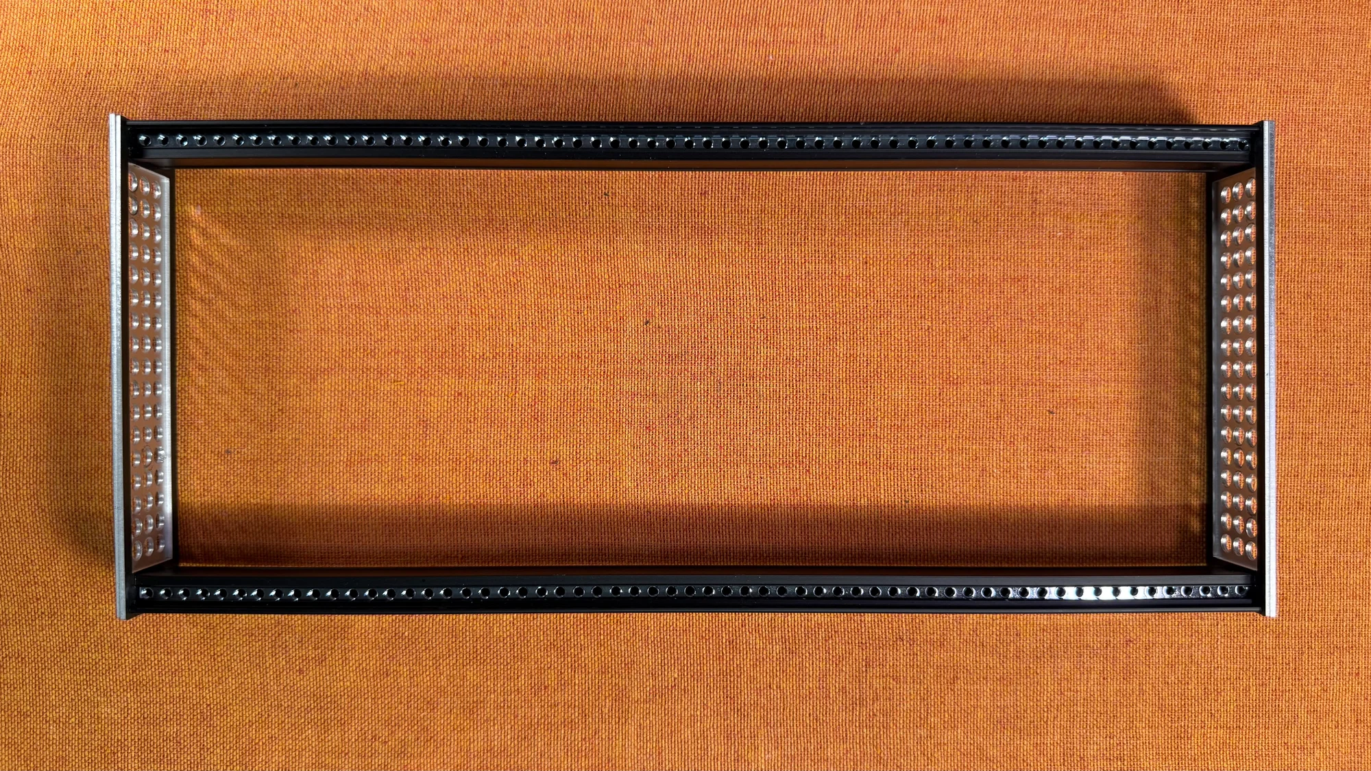
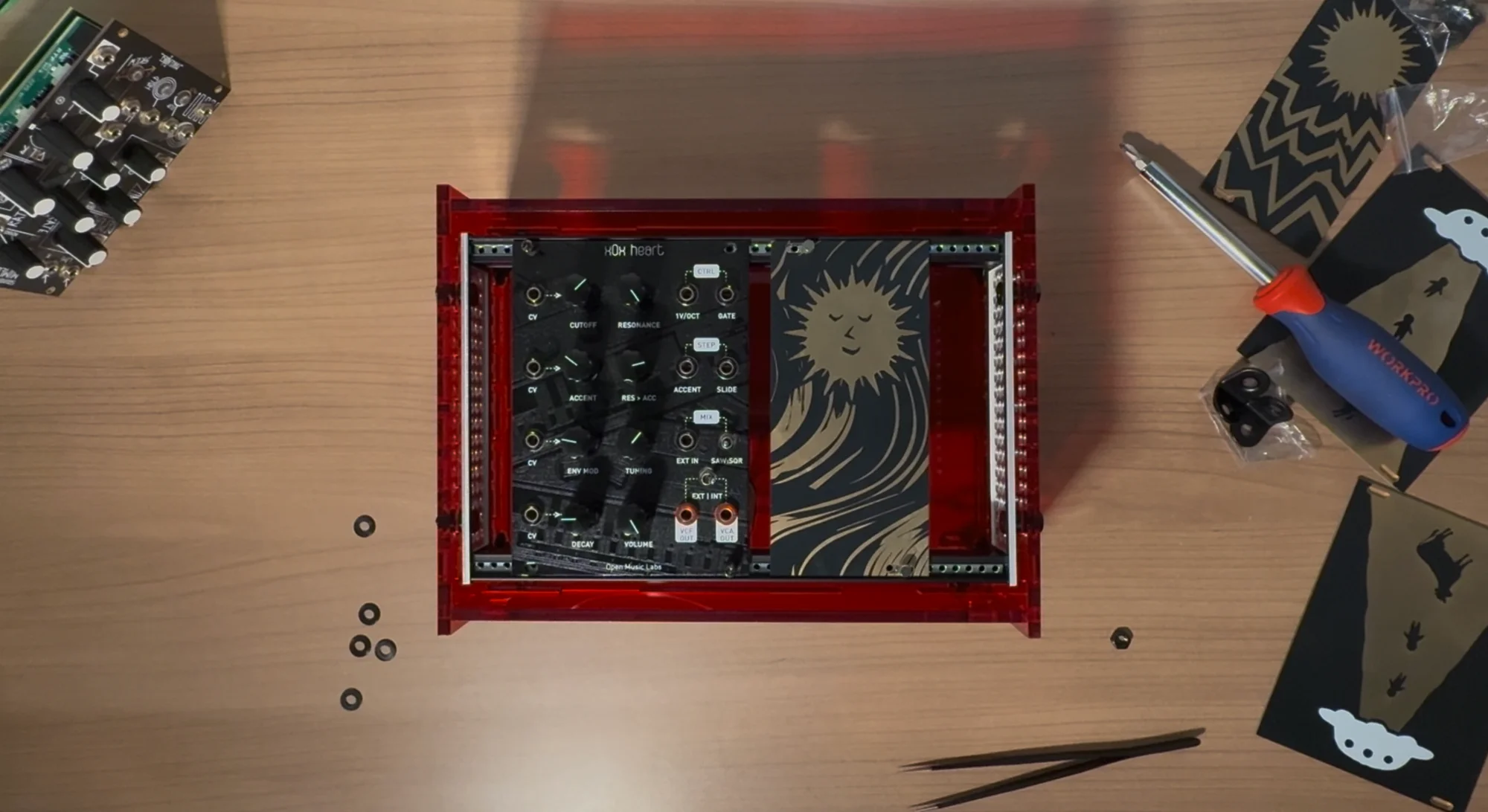
Completed Frame
40HP
60HP
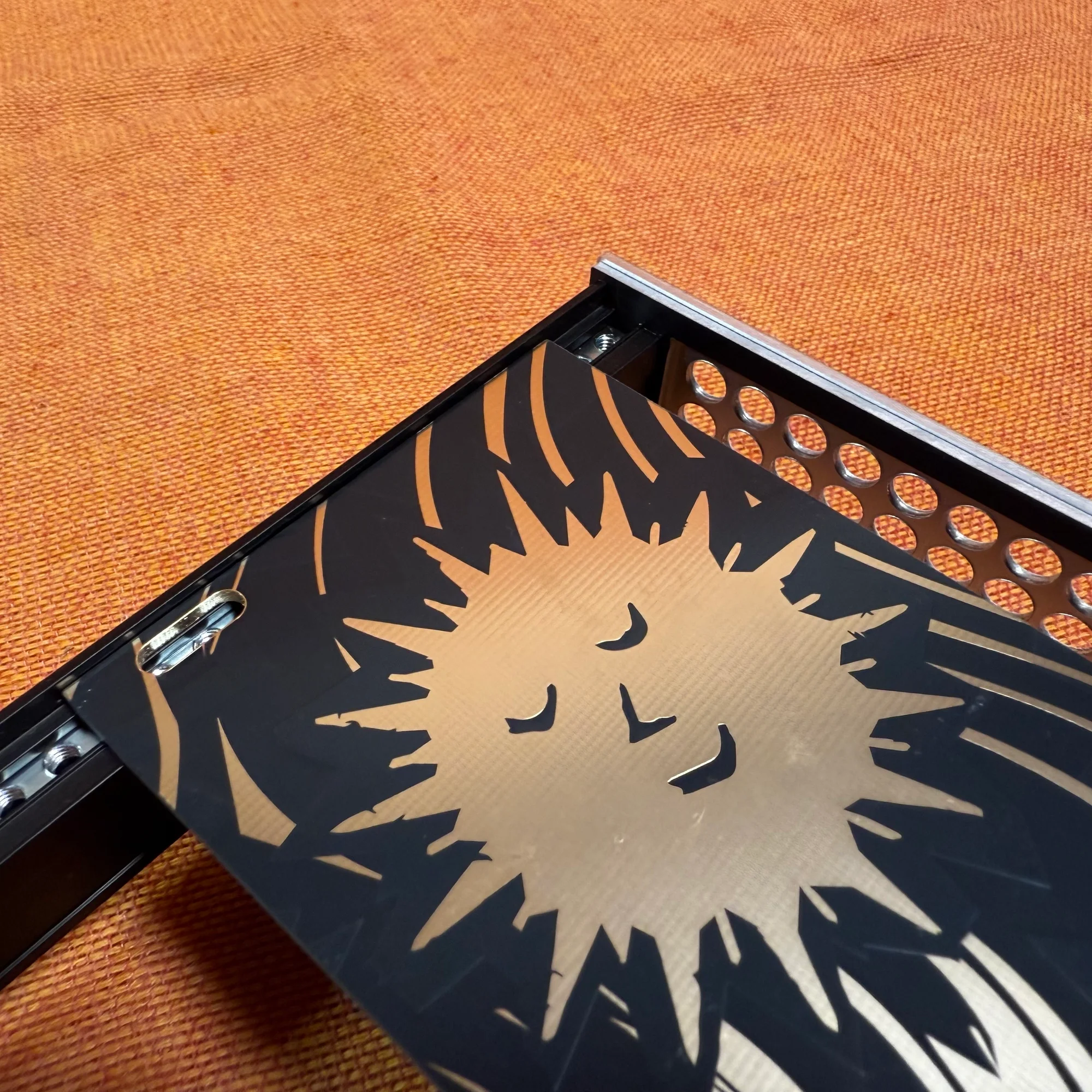
Step 3: Box Assembly
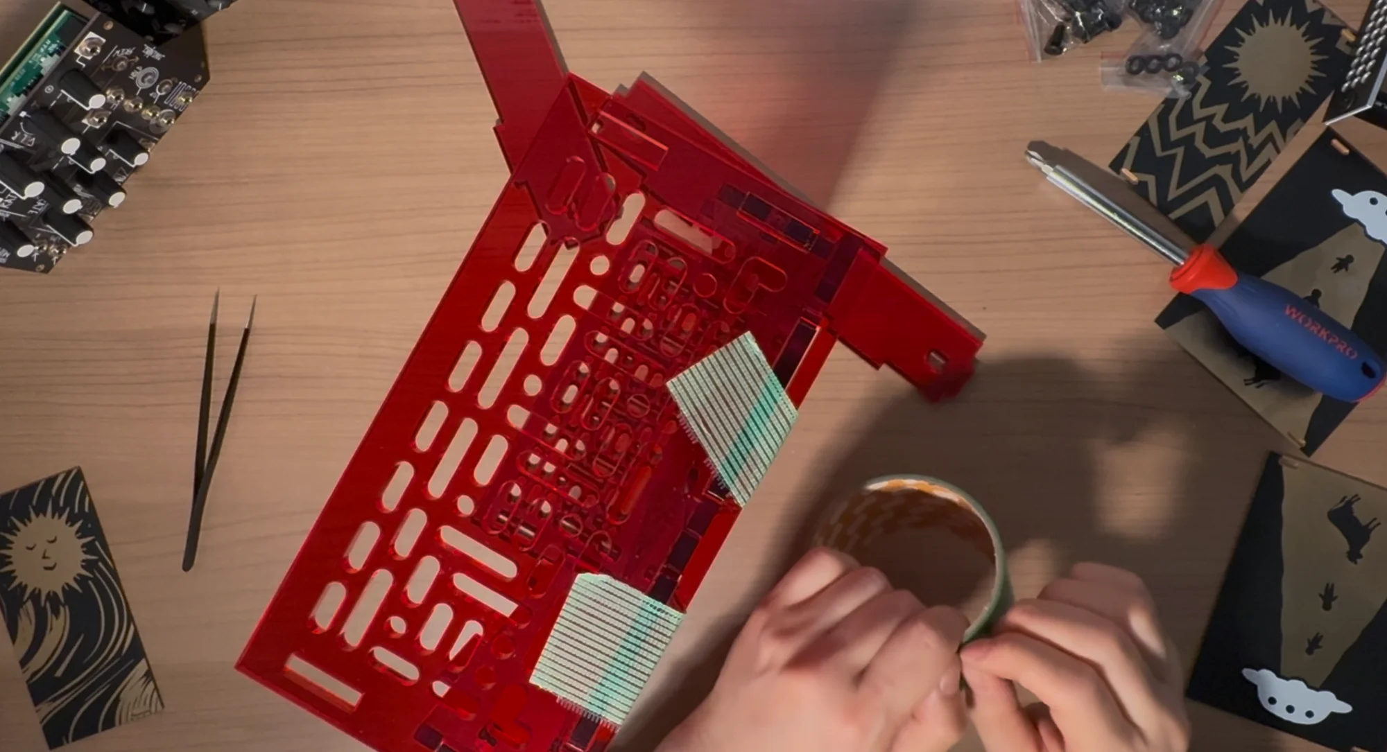
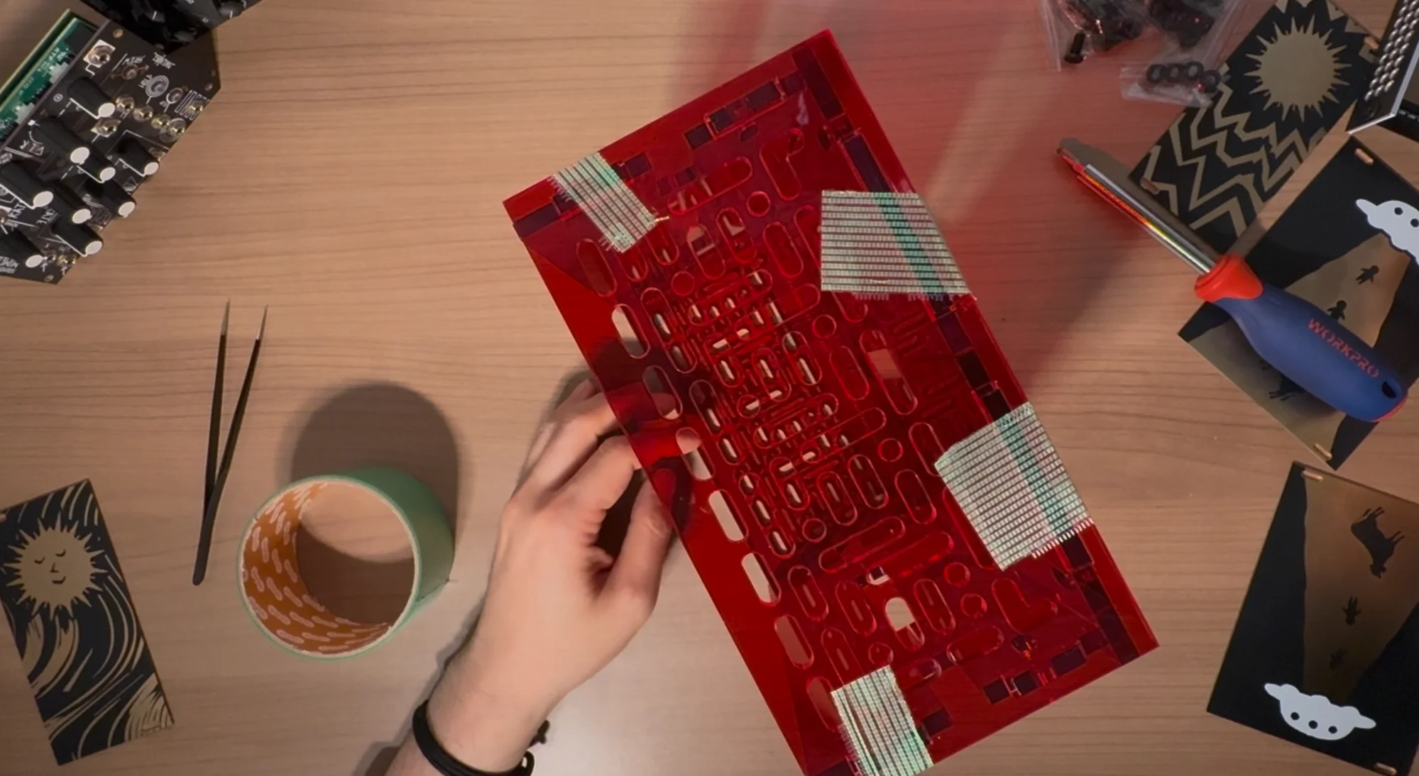
- Peel off the protective film from the acrylic boards.
- Insert the bottom panel and front/back panels into the larger holes near the edges of the side panels, then sandwich them with the other side panel. Make sure the side panels are symmetrical. For Type A side panels, ensure the hole patterns are aligned symmetrically on both sides.
- Temporarily secure the panels together with tape or similar.
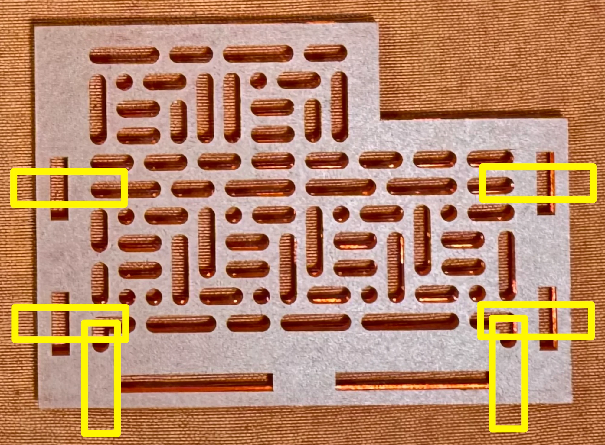
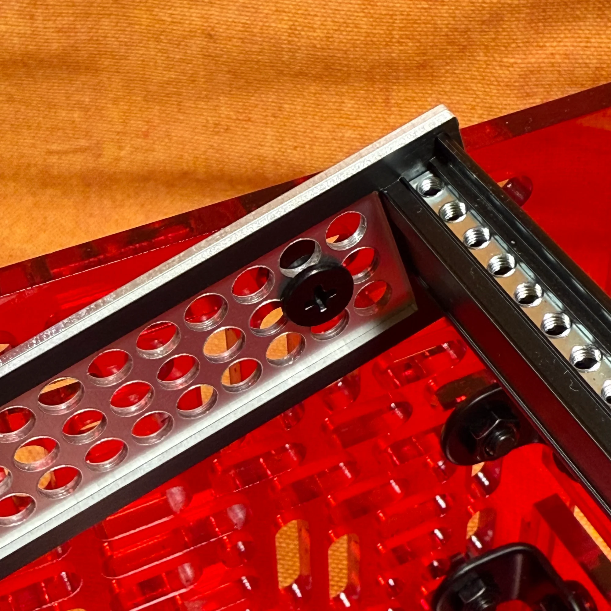
- Determine where to attach the panel-securing brackets. These brackets can be placed at the locations shown below, but it is possible to complete assembly without using any of them, and you do not need to use all six that are included. Consider the frame angle and position, and attach them where they won’t interfere with modules to securely hold the panels together.
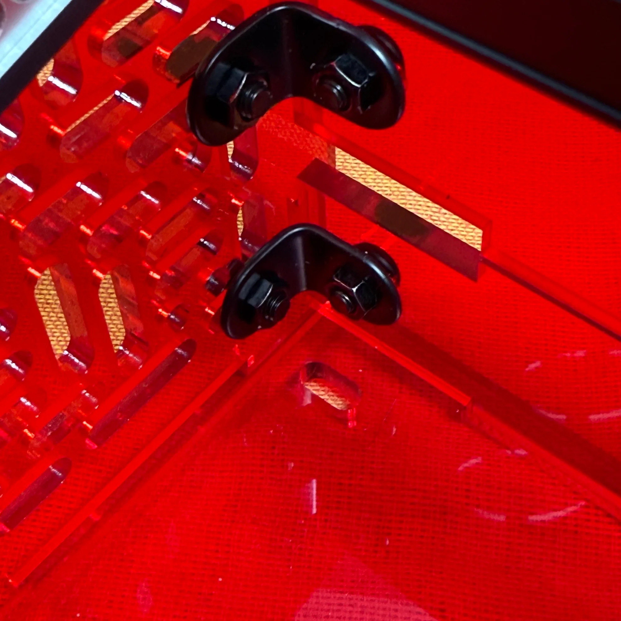
- Secure the panels together using the panel-securing brackets. Each bracket has two holes. From the outside inward, pass the components in this order: screw head, 1mm-tall washer, panel, bracket, nut — using M5 12mm screws. To make it easier to attach the frame in the next step, only loosely tighten the nuts at this point.
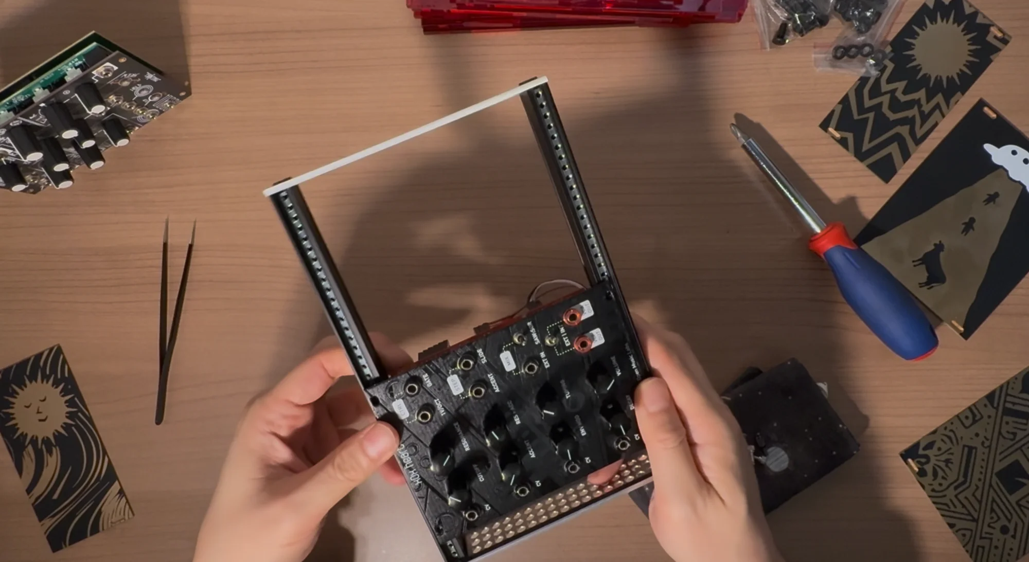
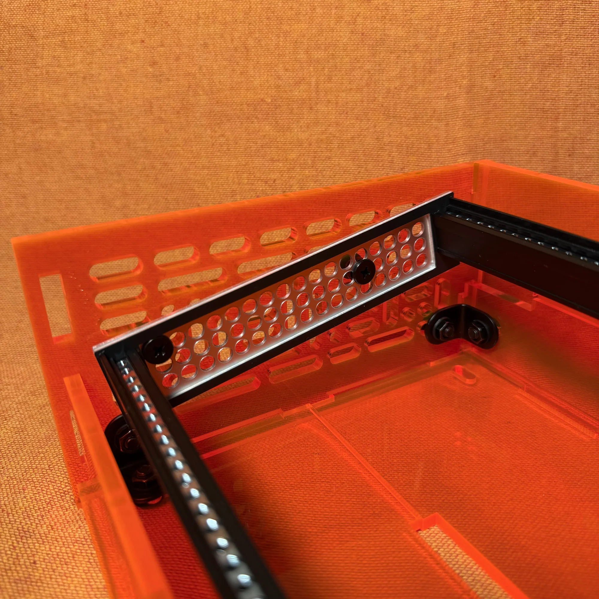
Step 4: Frame Mounting
- Place the frame inside the box and decide on your preferred position and angle. At this point, compare the holes on the side panels with those on the frame sides, and determine two positions for screw fastening in advance.
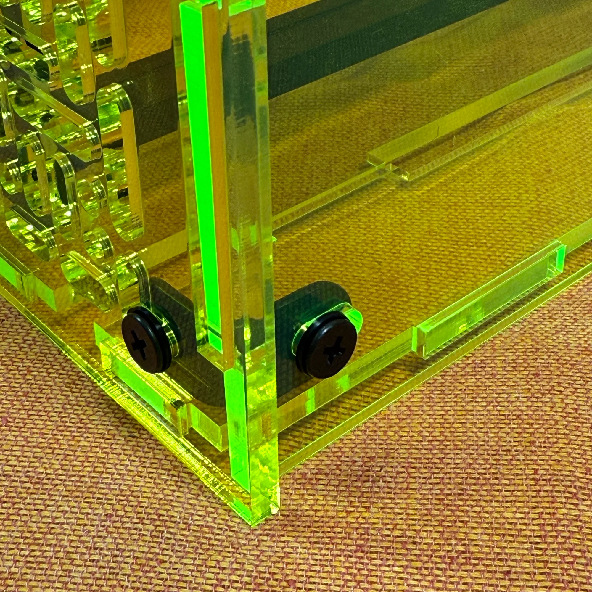
- From the inside, pass the components in this order: screw head, rail mounting panel, 3mm-tall washer, side panel, 1mm-tall washer, nut — using M5 14mm screws. Loosely tighten with the nut. Do this at two points. Think of it as placing the 3mm-tall washer in the space between the frame and the side panel.
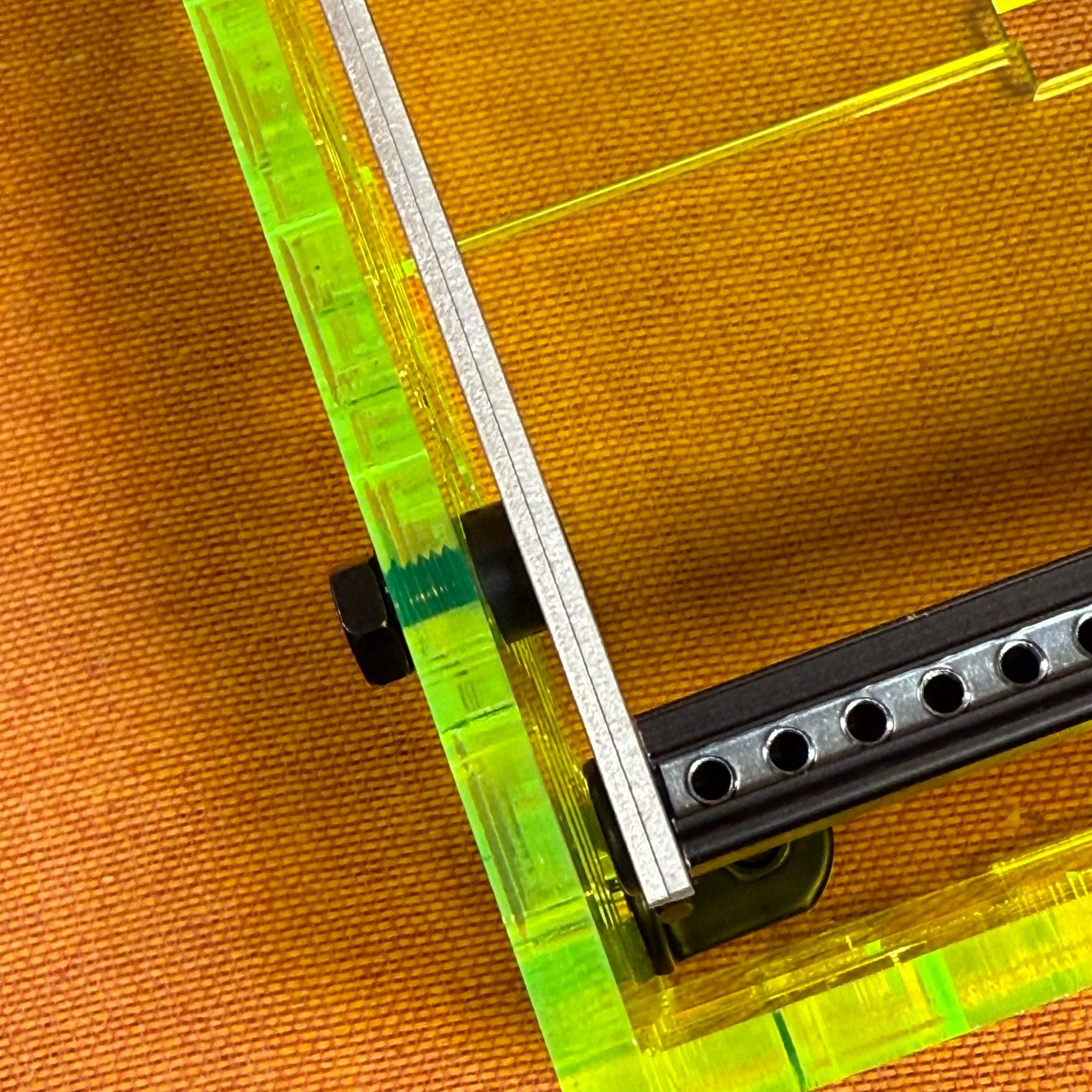
- Repeat the same process at the exact same positions on the other side panel, using M5 14mm screws, and loosely tighten the nuts.
- Place the box on a flat surface such as the floor, adjust the positions so the screws securing the left and right panels to the frame are at the same height on both sides, then firmly tighten the nuts with a wrench.
- Similarly, firmly tighten the nuts on the panel-securing brackets that were loosely fastened in Step 3. At this point, confirm that the bottom edges of the side panels sit flat on the floor so the box doesn’t wobble.
- Remove the tape that was used for temporary securing.
Assembly is now complete!
Assembly Tips
Here are some tips for assembly. Keep these in mind as you build.
- There are two types of short M5 screws: 12mm and 14mm. The longer 14mm screws are for securing the side panels to the frame, and all others are 12mm, so please be careful.
- During frame assembly in Step 2, if you’re using Metal rails, there is a step where you first drive M5 screws into the rails to create threads. This requires quite a bit of force.
- Due to the structural design of this case, once the side panels and frame are secured, the other panels are simply held in place by the slots in the side panels. You can actually complete the build without using the front, back, or bottom panels at all. Feel free to add or remove panels as needed for your setup.
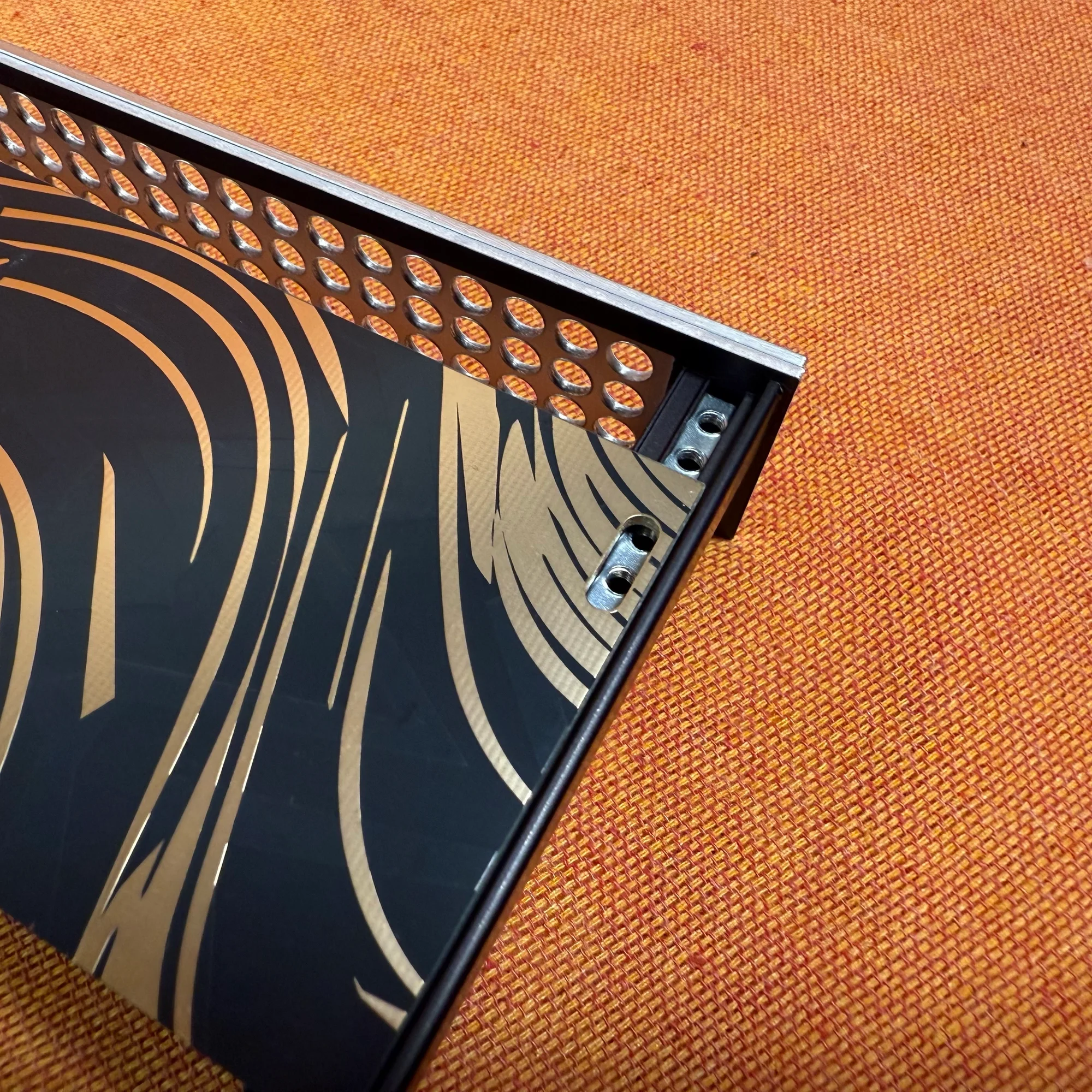
Adjustable Angle Design
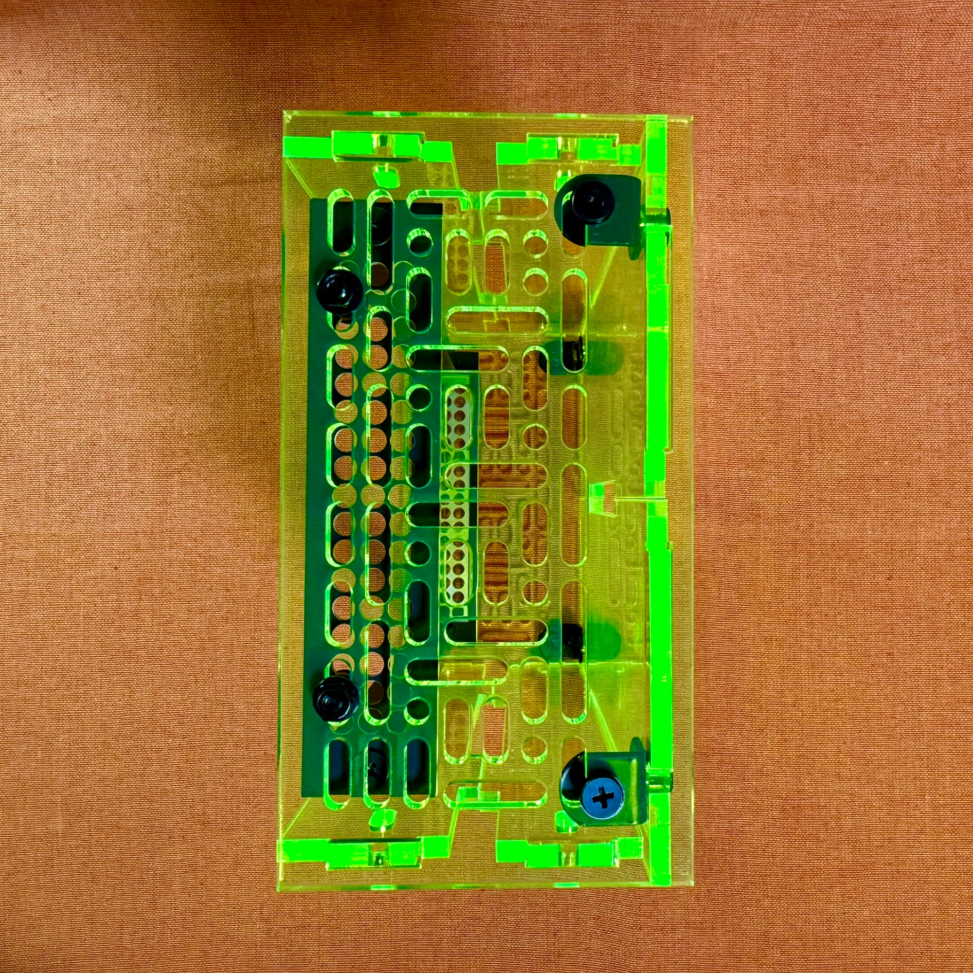
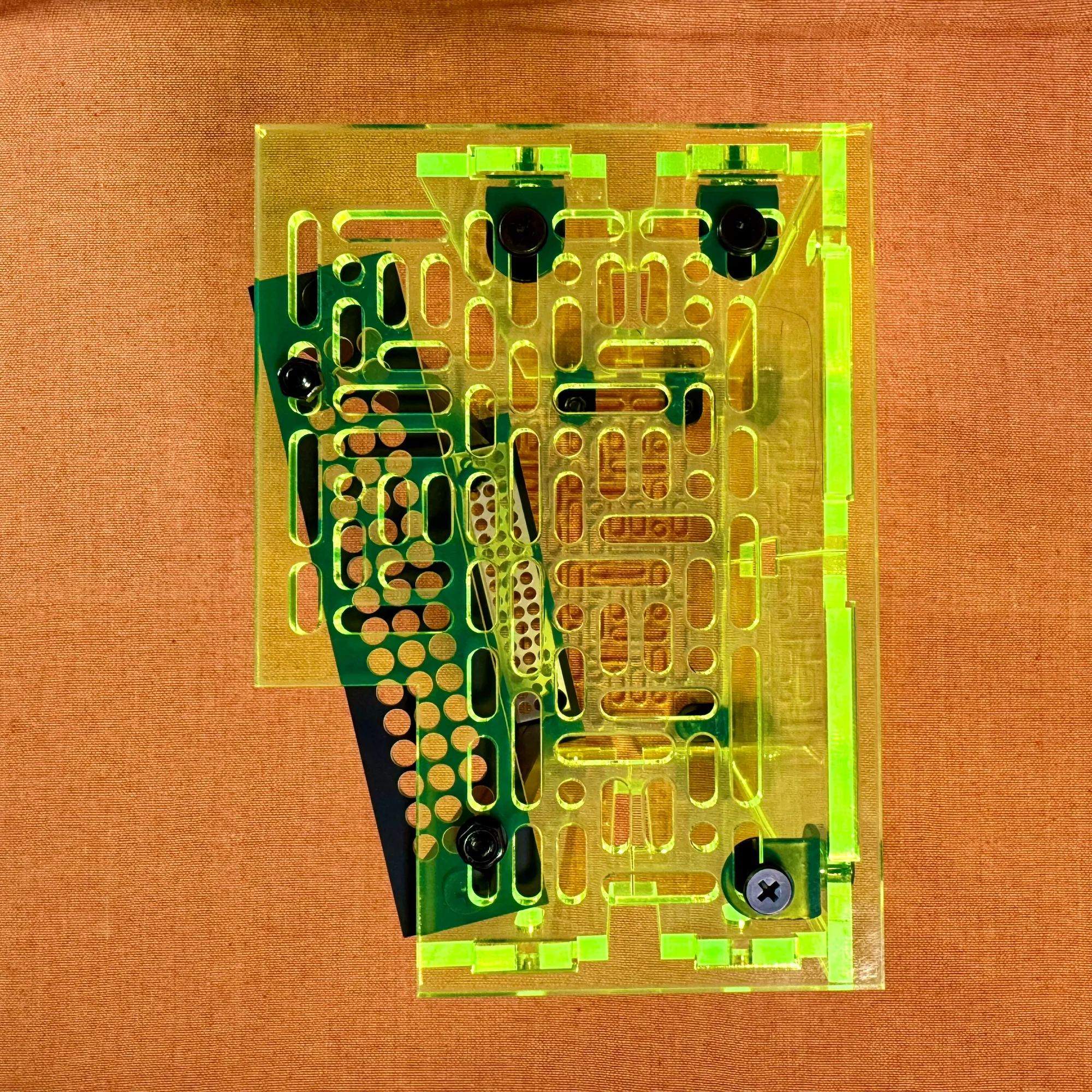
The box sides have many holes. These holes are sized to accept M5 screws, and you use the included M5 screws, washers, and nuts to align them with the holes on the frame sides for mounting.
Even with the Type A box, the depth is approximately 8cm, providing plenty of room to install a bus board at the bottom. Four front and back panels are included, but you don’t need to use all of them. If you tilt the frame at an angle and want a shallower profile, the panels may get in the way, so just use as many as you need.
As a personal recommendation, I suggest removing one front panel and tilting the frame slightly. If you’re not using deep modules, this still provides sufficient depth. It creates a nicely angled setup that makes the modules easier to operate.
That concludes the assembly guide for the zudo-block-40 / zudo-block-60.
For details on each product, please refer to the following pages: