This is an introduction to the ADDAC217 Quad Gate to Trigger by ADDAC System, available at Takazudo Modular.
The ADDAC217 is a 4-channel utility module that converts Gate signals into Trigger signals. It features per-channel bypass switches and converts Gate signals with temporal duration into 1ms Trigger signals.
This product is available for purchase below.
Takazudo Modularではマニュアル等の日本語訳付きを作成し、公開しています。以下よりご参照下さい。
- Product Photos
- The Difference Between Gate Signals and Trigger Signals
- ADDAC217 Functionality
- Signal Flow Diagram
- Reference Video
- Technical Specifications
- Included Accessories
- Manual
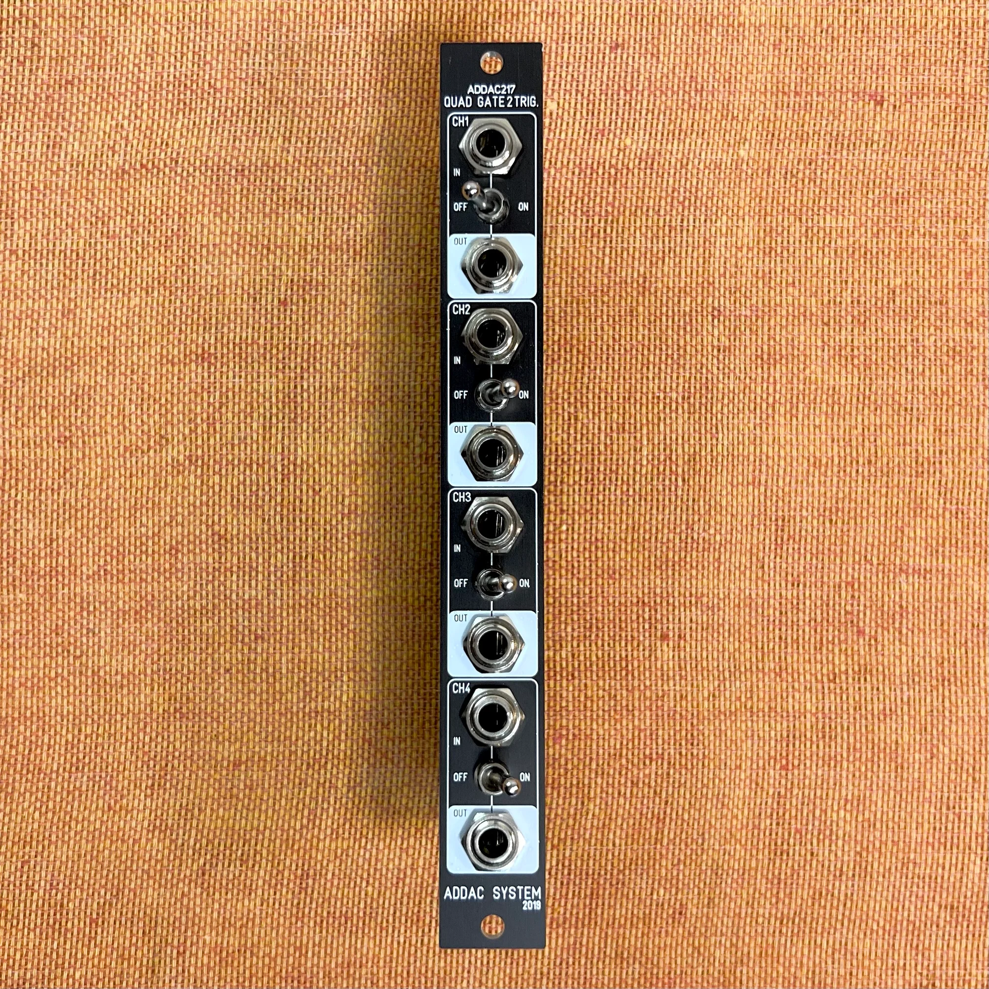
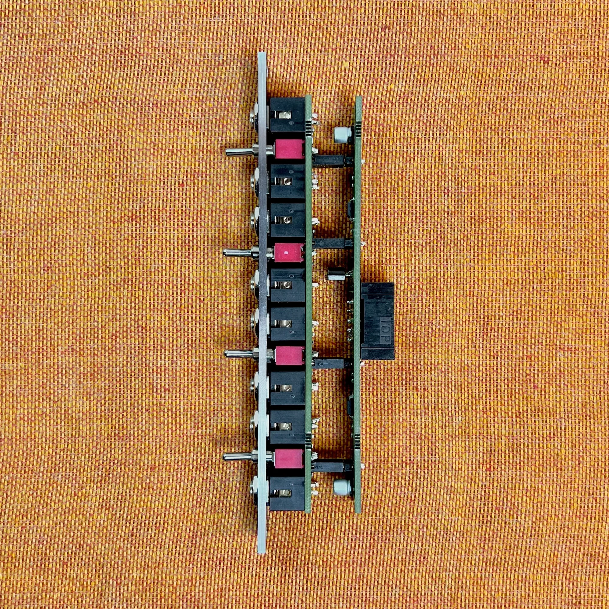
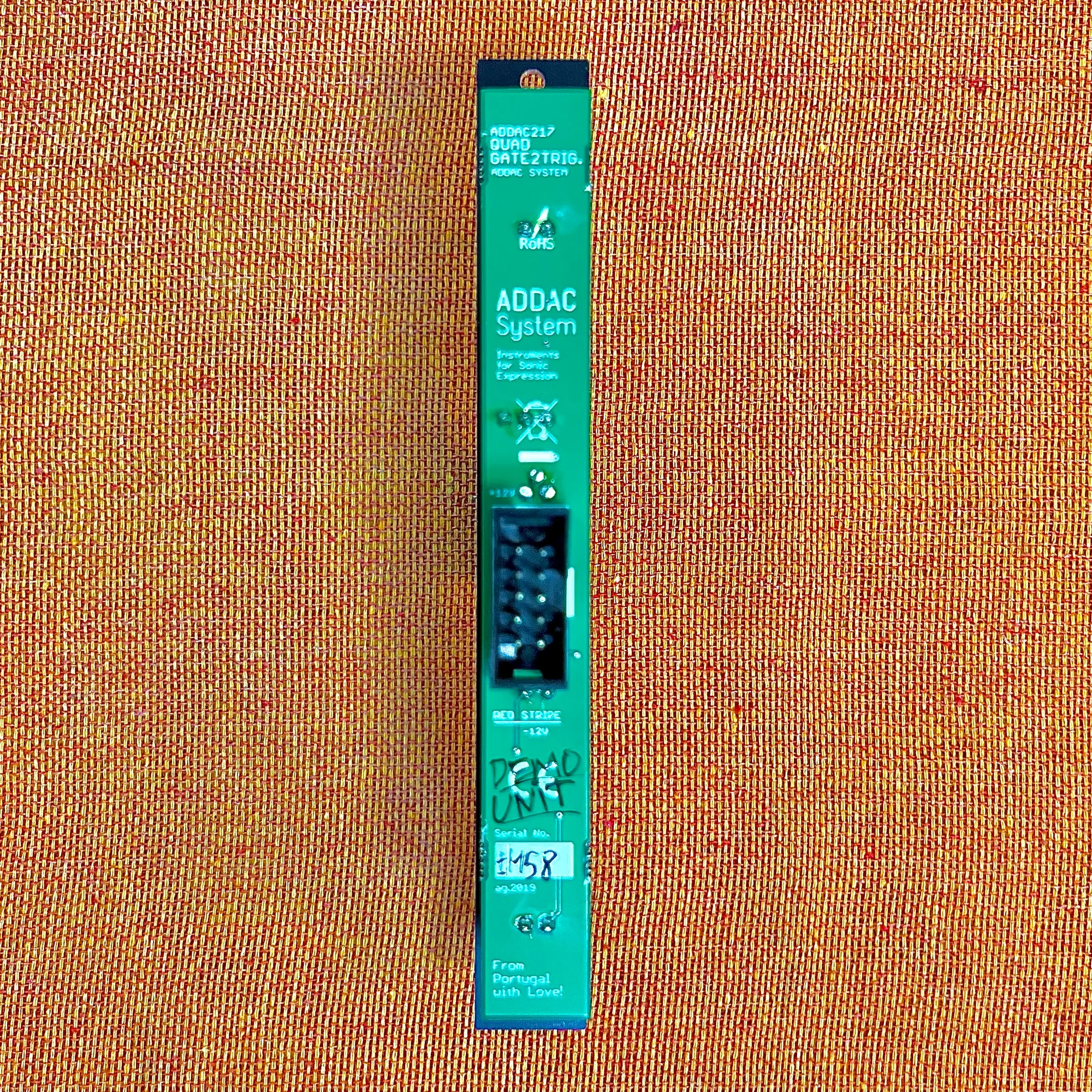
Product Photos
The Difference Between Gate Signals and Trigger Signals
Before explaining this module, let me first touch on the difference between Gate signals and Trigger signals.
What Is CV?

As a quick review of terminology: what flows between jacks in a modular synthesizer via patch cables is electrical current. Each module applies approximately +12V to -5V of voltage to the copper wire inside the cable, using the magnitude of that voltage as a signal. After various electronic components process these signals, the final result drives a speaker cone up and down to produce sound.
Each module has numerous jacks. For example, an oscillator might have 1V/Oct and FM Modulation jacks, while a low-pass filter might have Cutoff and Resonance jacks. These jacks allow you to control each parameter externally.
These are input jacks that connect via patch cables to output jacks on other modules, applying voltage as described above, using its magnitude as a signal to control things like 1V/Oct and Cutoff. Voltage used specifically for controlling a modular synthesizer is called CV (Control Voltage).
What Is a Gate Signal?
Within CV, there are cases where you need ON/OFF, two-state information. For example, CV used to trigger a drum module, CV used to advance a sequencer by one step, or CV used to trigger a hold in a Sample & Hold module.
Such CV is expressed as two states — a low voltage state (0V) and a high voltage state (e.g., +5V) — where the high voltage state is treated as ON.
This type of CV is specifically called a Gate signal or Gate CV.
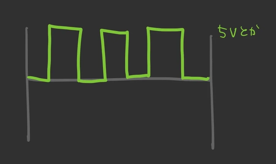
What Is a Trigger Signal?
In contrast, a Trigger signal or Trigger CV looks like this:
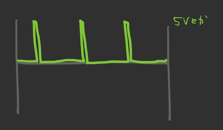
Like the Gate signal described above, it is a CV expressing ON/OFF two-state information, but with Trigger signals, the ON state duration is very short.
Gate Signals vs. Trigger Signals
However, these two types are not often clearly distinguished by name. Generally, “Gate” tends to be the more commonly used term. This is because many modules do not actually use the time duration of the Gate in their functionality.
For example, consider the Kick V2 kick drum module below.
This module’s TRIG input generates a kick drum sound when it receives CV above a certain threshold (e.g., 2.5V or higher) and outputs it from the OUT jack.

In this case, the duration of the CV does not matter. Since Kick V2 creates the kick sound at the moment it receives CV above the threshold, the length of the subsequent ON state has no effect on this module’s function. Therefore, in this case, it makes no difference whether you send a Gate or a Trigger to Kick V2.
Since the duration of the ON state is irrelevant in many cases like this, CV that expresses ON/OFF is generally just called “Gate.” Personally, I (Takazudo) rarely use the word “Trigger” in everyday usage.
ADDAC217 Functionality
Now, returning to the ADDAC217’s functionality: this module converts Gate signals into Trigger signals with a duration of 1 millisecond. Wait — did I not just say Gate and Trigger are basically the same thing? Well, there are cases where this difference does matter.
ADDAC106 T-Noiseworks
ADDAC System notes on this module’s product page that they realized during the development of the T-Networks series how important it is to select the appropriate type — Gate or Trigger — when triggering drum modules or Envelope Generators.
Among the ADDAC System modules we carry, the ADDAC106 T-Noiseworks is a module where the difference between Gate and Trigger is clearly apparent.
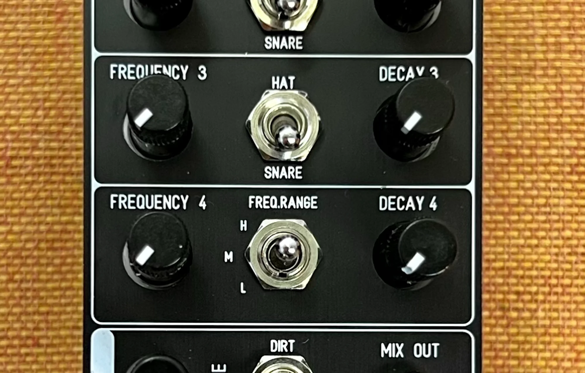
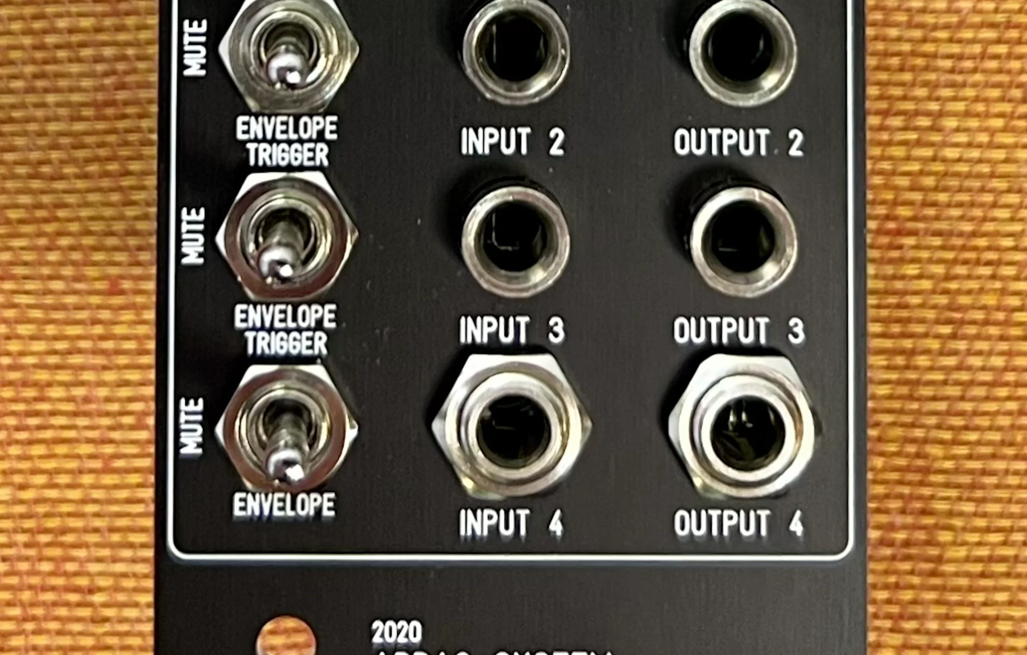
T-Noiseworks has a mode switch on each channel. When set to TRIGGER, it works like the Kick V2 described earlier — generating audio at the moment it receives a high voltage, with the decay time set by the DECAY knob.
In contrast, when this switch is set to ENVELOPE TRIGGER, the decay time increases proportionally to the duration of the CV received at INPUT. So in Envelope Trigger mode, if the CV received at INPUT is a Gate, the volume decay time becomes longer.
This module generates sound based on white noise. As a result, when receiving a long Gate, the sound has a long release character like a sustained “shhhh-shhhh,” whereas when receiving a Trigger, the short decay time produces a punchy, attack-forward sound like “ch-ch.”
ADSR Envelope Generator + VCA
The same applies when controlling an oscillator’s output with a VCA and ADSR Envelope.
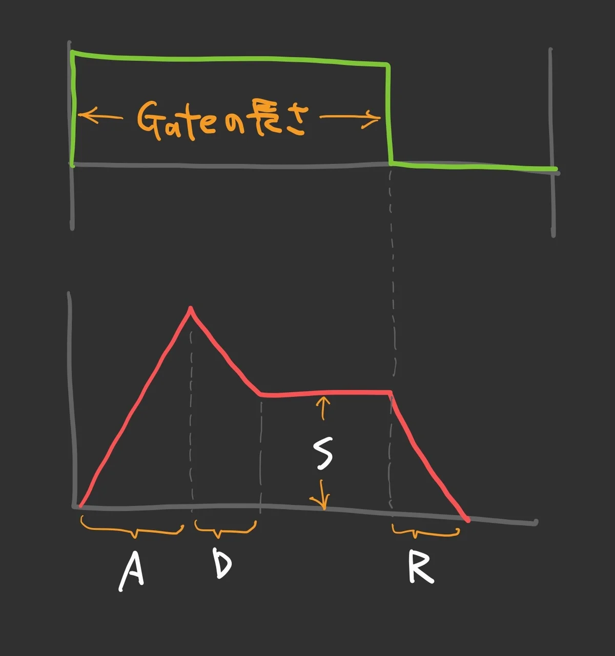
In a typical ADSR Envelope module, the ON duration corresponds to the ADS portion of the envelope.
For example, with an envelope set to Attack at 0 and Decay/Sustain/Release at moderate values, a Gate would produce a gradual decay through Decay, Sustain, and Release, while a Trigger would immediately jump to the Release stage — creating a distinctly different result.

Since the ADDAC217 has bypass switches, you can normally leave the bypass off to pass Gate signals through unchanged, and temporarily switch to Trigger when you want a more attack-forward sound — enabling real-time performance control.
Understanding this difference can help clarify what you need to do to achieve the sound you are aiming for.
This module packs 4 channels into just 3HP, making it a compact yet versatile utility for casually converting Gates to Triggers whenever needed.
Signal Flow Diagram
The ADDAC217 is a very simple module. As shown below, it converts Gate signals received at IN into Triggers and outputs them at OUT. As mentioned, the bypass switch lets you toggle whether this conversion is applied.

Reference Video
Below is a tutorial video from the official ADDAC System YouTube channel about the ADDAC217. You can hear the difference between Gate and Trigger demonstrated with the ADDAC106 T-Noiseworks mentioned above.
Technical Specifications
- Width: 3HP
- Depth: 25mm
- Power consumption: 10mA +12V / 10mA -12V
Included Accessories
- Power ribbon cable
- Screws
Manual
The manual is available on the official website below.
ADDAC Systemについて
ADDAC Systemはポルトガルのモジュラーシンセメーカーです。
アナログ良さを生かした、ベーシックな機能をしっかり形にしているモジュールラインナップを基本としつつも、CVをMIDIに柔軟にコンバートしたり、高度にコントロール可能なグラニュラープロセッサー等、デジタル技術もうまく調和させた独創的なモジュールも数多くリリースしています。
オマケ: 電氣美術研究會モジュラー小物セット付き

モジュラーシンセをもっと多くの方に触って欲しいという願いの元、電氣美術研究會さまにご協力頂き、モジュラー小物セットを本商品にバンドルさせて販売させていただいております。
パッチケーブルや電源ケーブル、ドレスナットのサンプルセット、モノラルスプリッターなど、内容は時期に応じて変化します。商品に同梱しますので是非お試し下さい!
That concludes the introduction to the ADDAC217 Quad Gate to Trigger.
Takazudo Modularではマニュアル等の日本語訳付きを作成し、公開しています。以下よりご参照下さい。
We hope you found this helpful.