This is an introduction to Takazudo’s DIY series product, zudo-bus.
This is a bus board designed for use with the separately sold zudo-block-40. Of course, it can also be used with cases you’ve built yourself through DIY. Feel free to use it as a convenient power distribution solution.
This product is available in both pre-built and DIY kit versions, available for purchase below.
- Product Photos
- zudo-bus Features
- Basic Usage
- Setup Examples
- +5V Voltage Supply
- Power Input via Faston Terminals
- About Power Supply
- Included Items
- DIY Kit Assembly Instructions
- Terms of Use
- Specifications
- BOM
Product Photos
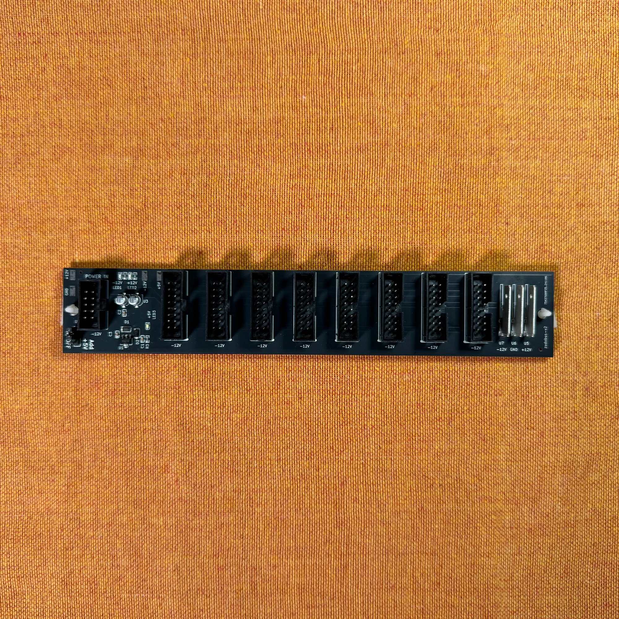
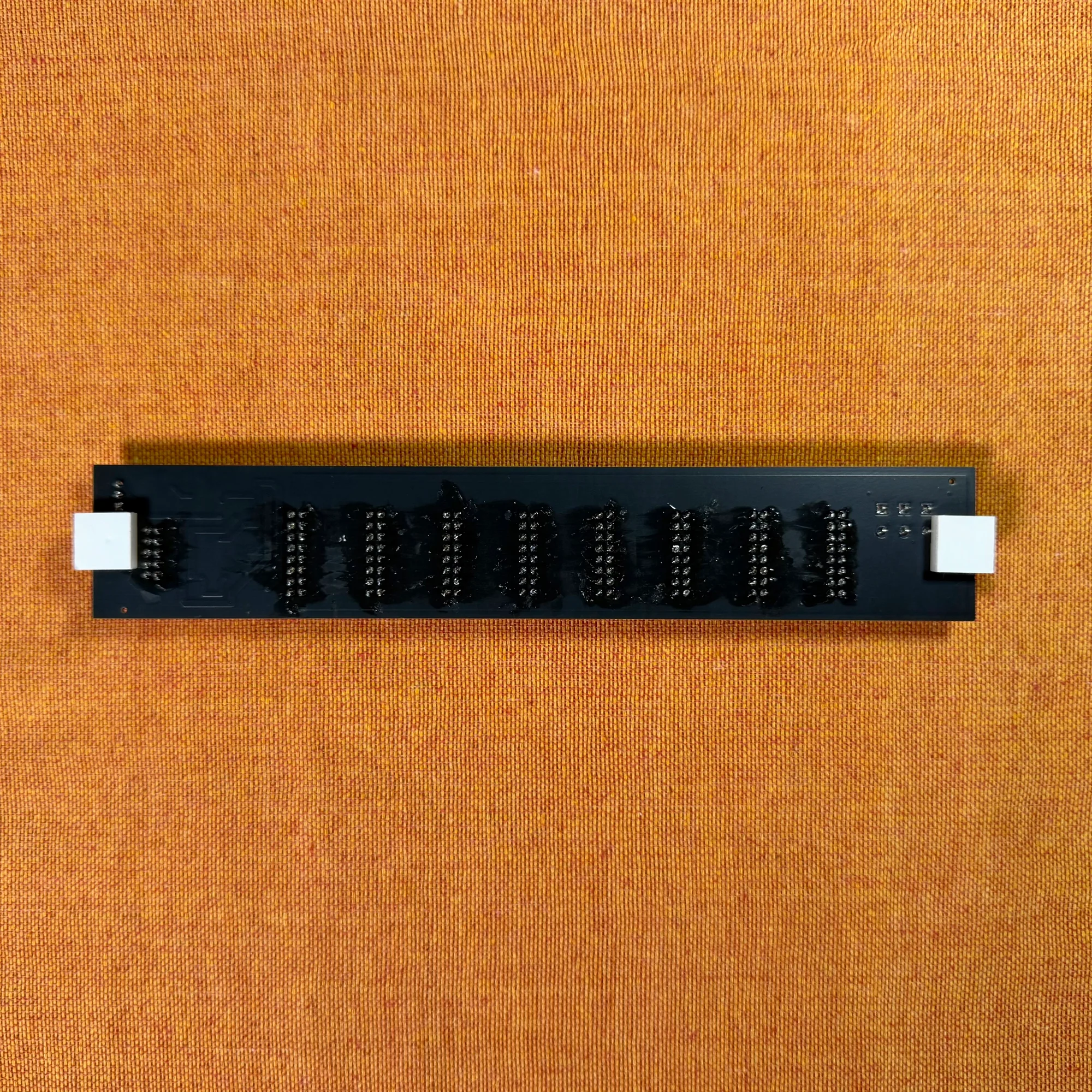
Pre-Built
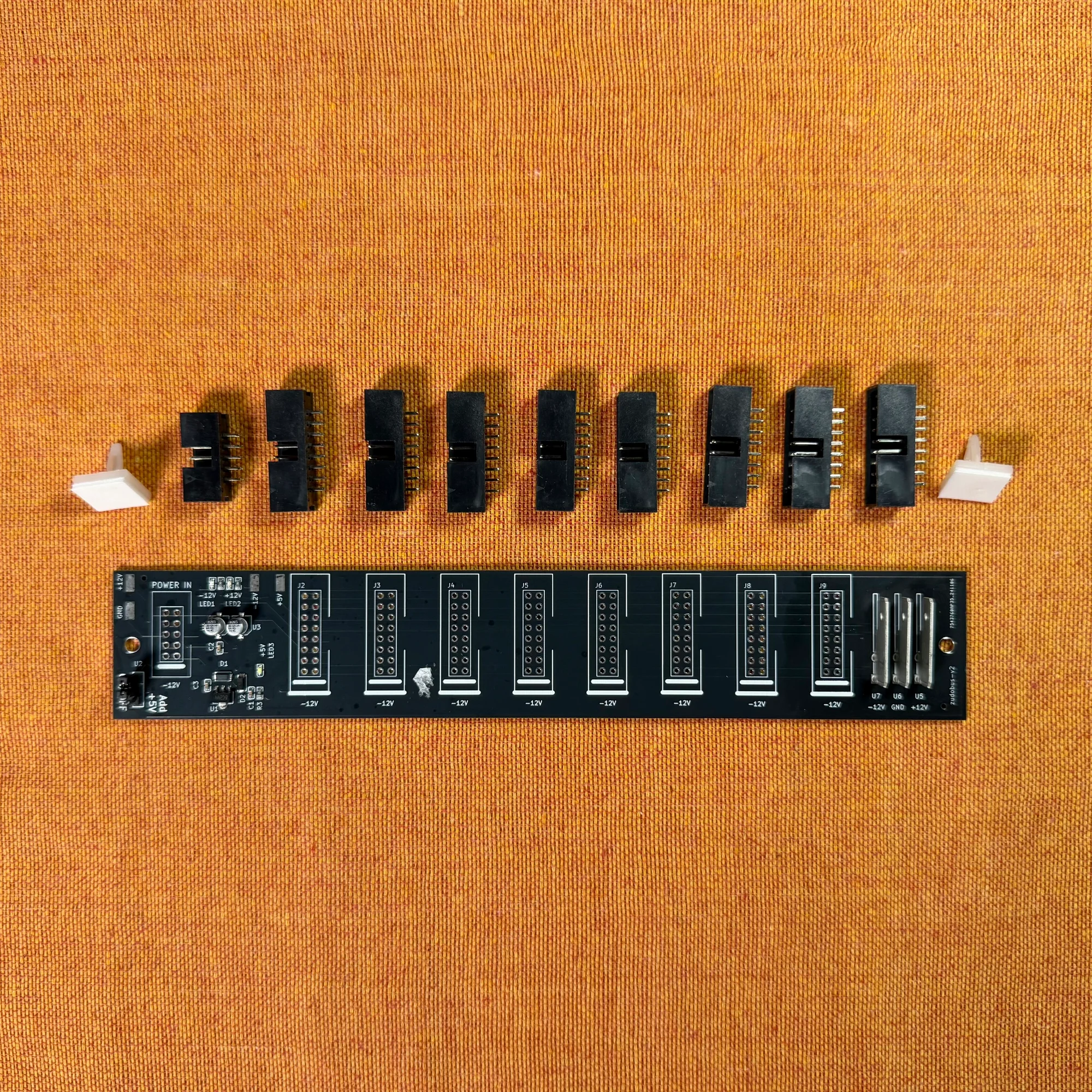
DIY Kit
zudo-bus Features
The zudo-bus is a PCB that distributes power from a power source to multiple modules. In Eurorack modular synthesis, mains voltage is regulated for module use and then distributed to each module. The power distribution role is typically handled by a bus board built into the case when you purchase one, or by dedicated power supply modules (discussed later).
If you’re using a case with a built-in power supply, it likely already has a bus board, making this zudo-bus unnecessary. However, for cases without built-in power—like the zudo-block-40 we sell separately—the zudo-bus can be used for power distribution.
The zudo-bus receives +12V / -12V / GND via a 2x5 10-pin connector (or faston terminals) and distributes it to each module. It also includes a +5V voltage supply feature. The white feet visible in the photos have adhesive tape on the bottom for securing the board to your case.
Basic Usage
This bus board is designed to be used in conjunction with a separate power supply device. Please note that the bus board alone cannot generate the voltage needed to power modules.
The zudo-bus receives power input through the 2x5 10-pin connector on its left end. For this usage explanation, let’s assume you have a separate powered case and are using a long power ribbon cable to supply power. Simply connect the cable to the left-end 10-pin connector as shown below, and power supply is ready. You can verify connection by checking that the on-board LEDs are lit.
Note: Always connect and disconnect cables with the power OFF.
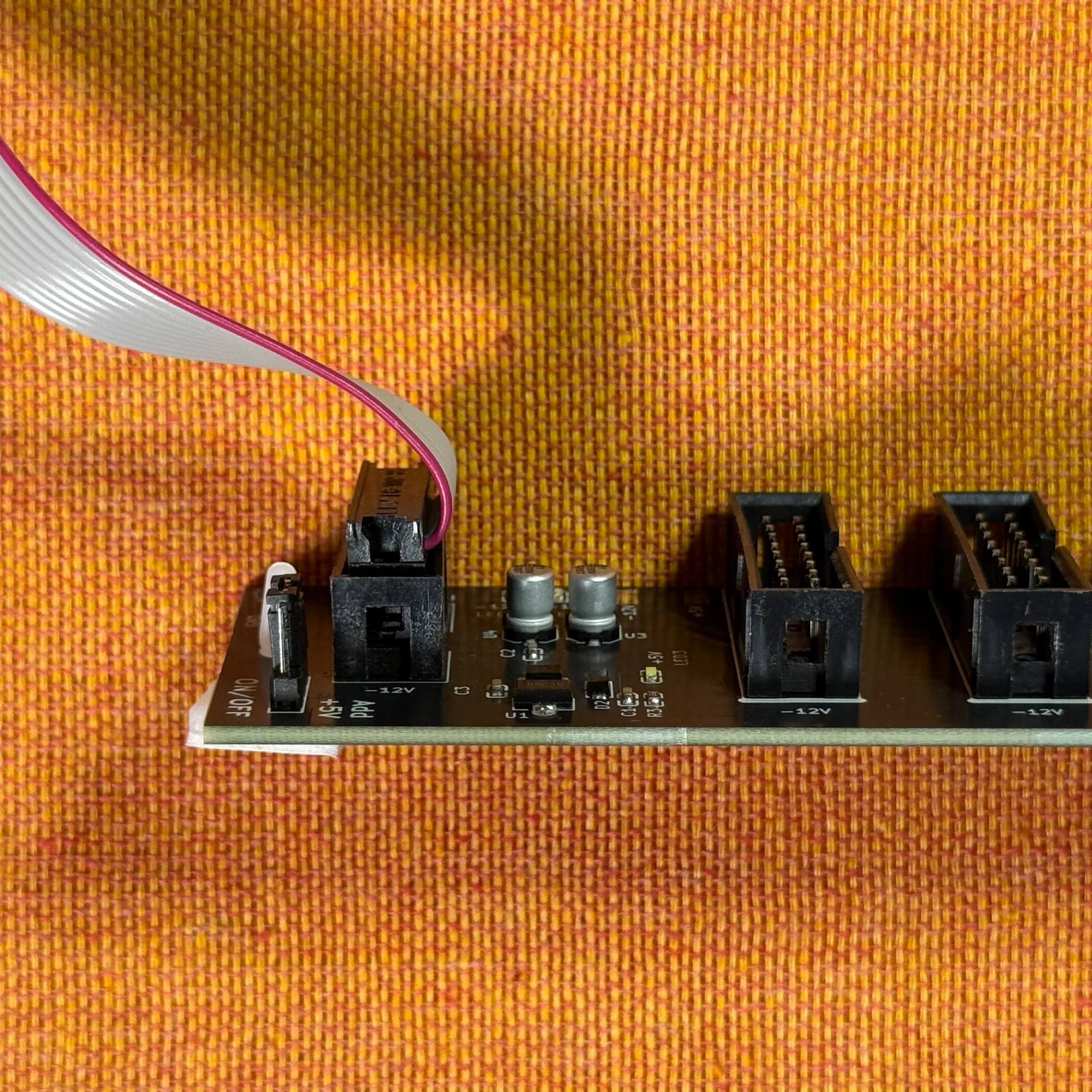
Once you’ve confirmed the LEDs are lit, connect your modules to the other sockets using power ribbon cables.
That covers the basic usage.
Setup Examples
As mentioned, the zudo-bus was designed for use with the zudo-block-40. This section introduces some setup examples using the zudo-bus.
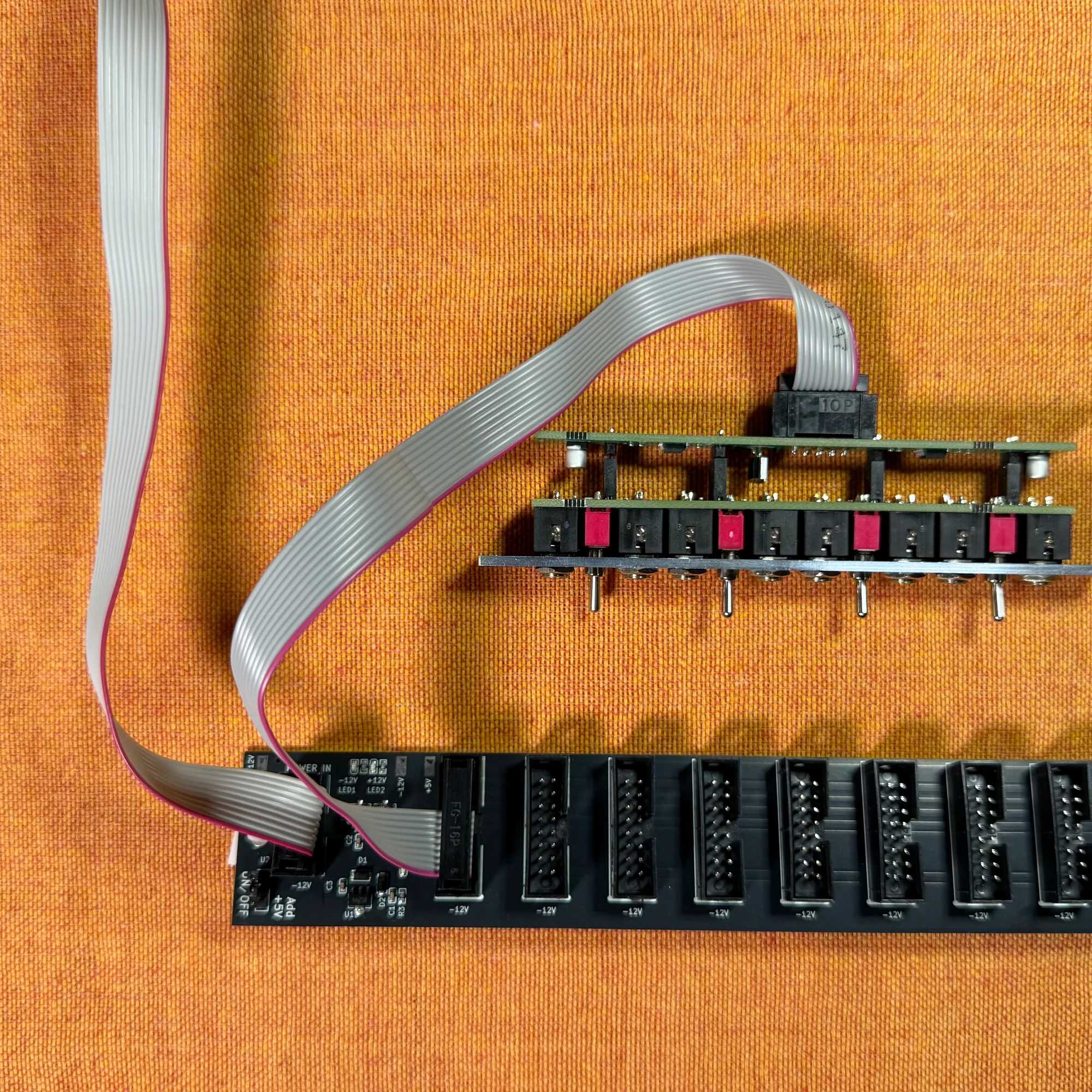
Example 1: Simple Power Connection
The simplest setup is having an external power supply that feeds power to the bus board.
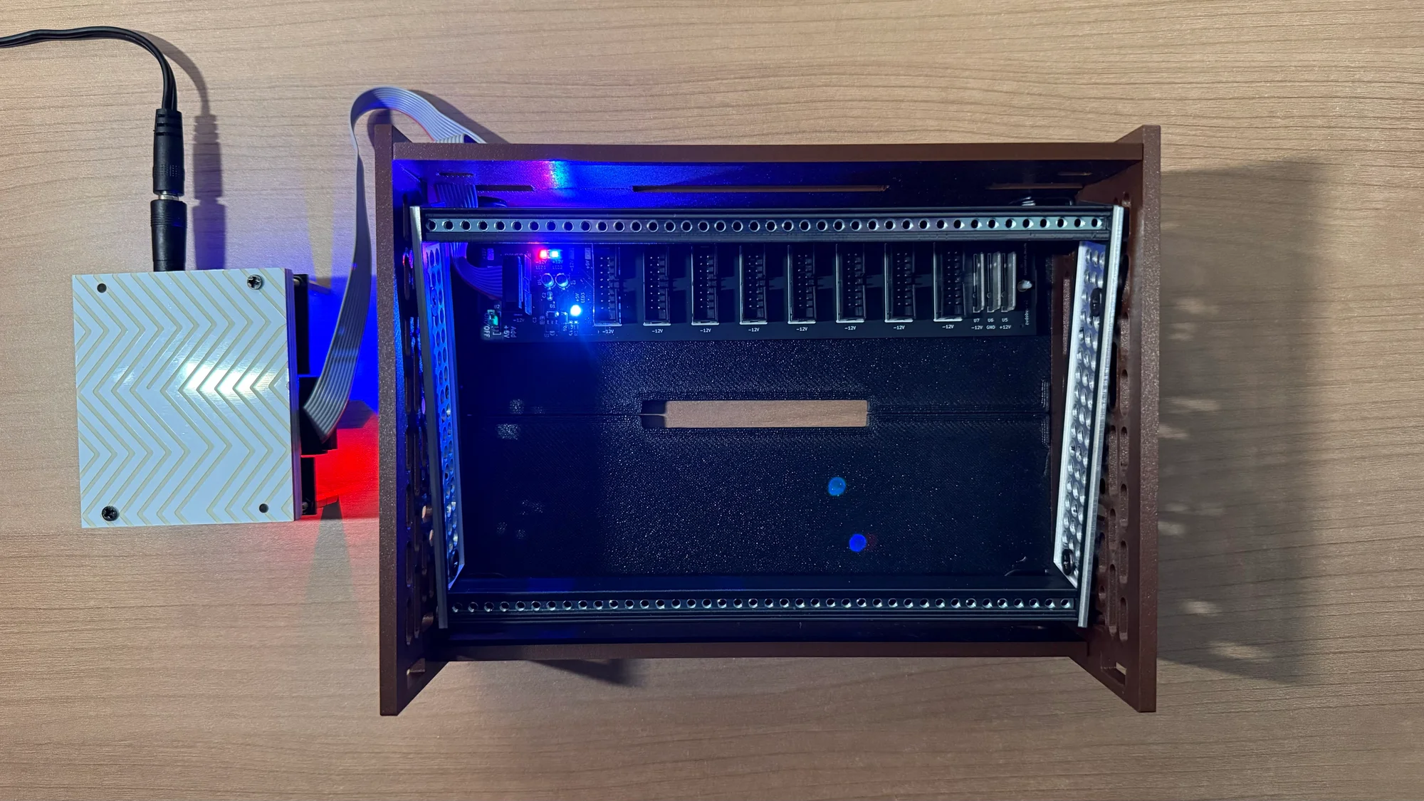
The power supply shown in this photo is a prototype under development, but the same principle applies when receiving power from a larger parent case or a power supply module.
Example 2: Multiple Cases
This is a setup example where an additional case is added to Example 1.
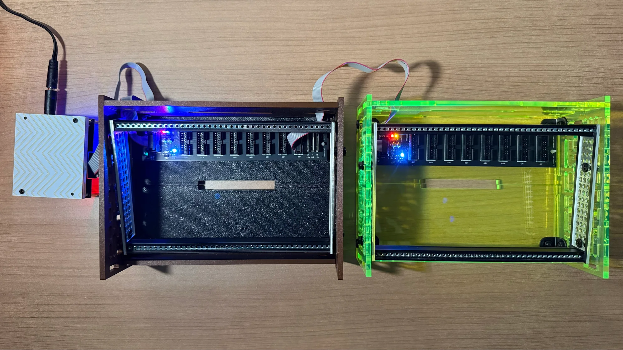
In this setup, a power ribbon cable is connected from the right-end pin of the left zudo-bus to the input of the right zudo-bus. This connects the right zudo-bus to the power supplied through the left zudo-bus.
Example 3: Combined with a Power Module’s Daisy Chain
This example uses a Behringer: CP1A as the power source.
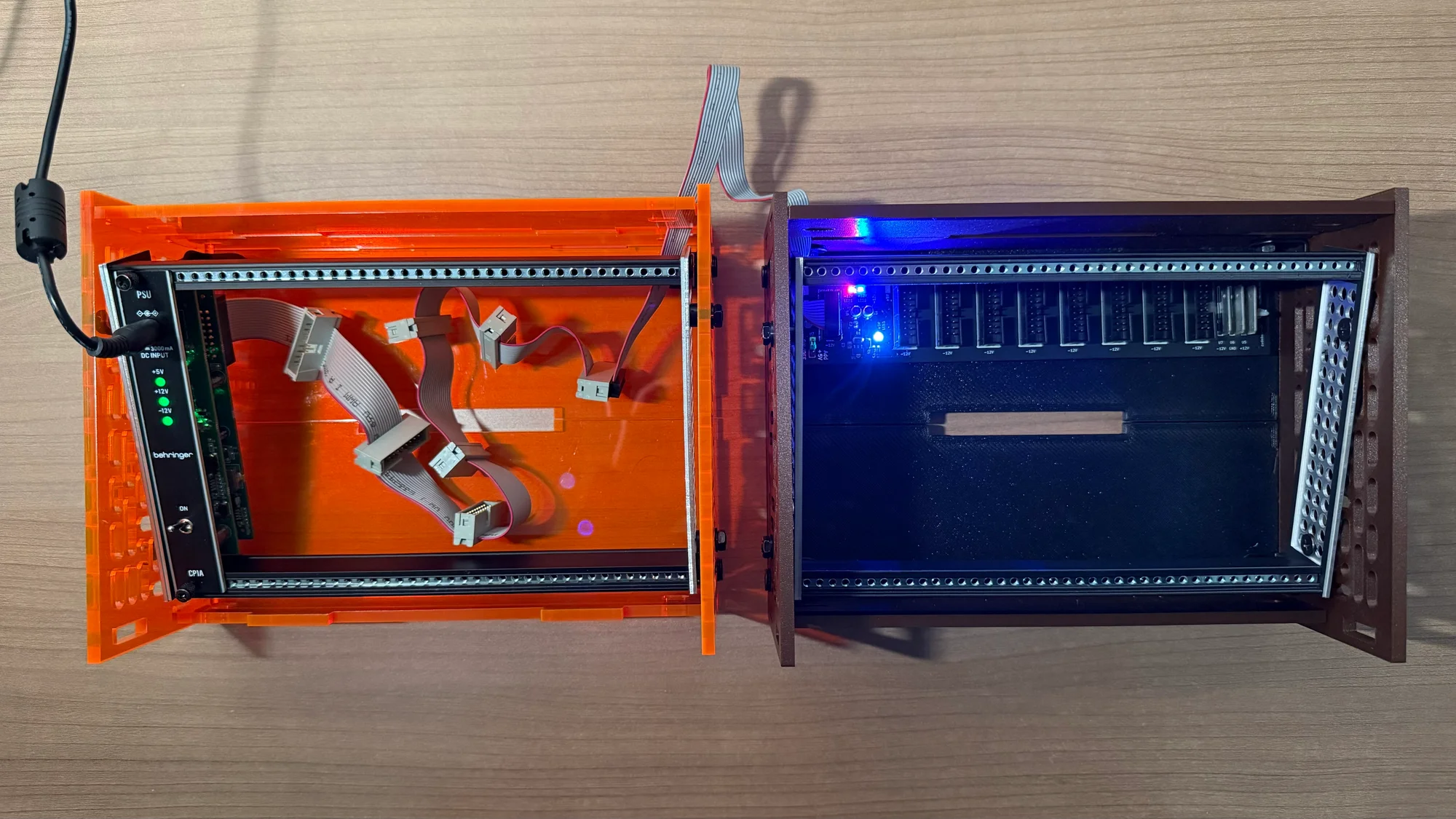
The left case uses the daisy-chain cable included with the CP1A, while the right zudo-bus receives power via a power ribbon cable extended from one of the daisy-chain outputs, distributing it to the modules in the right case.
In this configuration, you could also install a zudo-bus in the left case and connect the CP1A output directly to the zudo-bus without using the daisy chain.
+5V Voltage Supply
This bus board connects to the power source through three circuits:
- +12V
- GND
- -12V
Therefore, it does not receive +5V voltage from the power source.
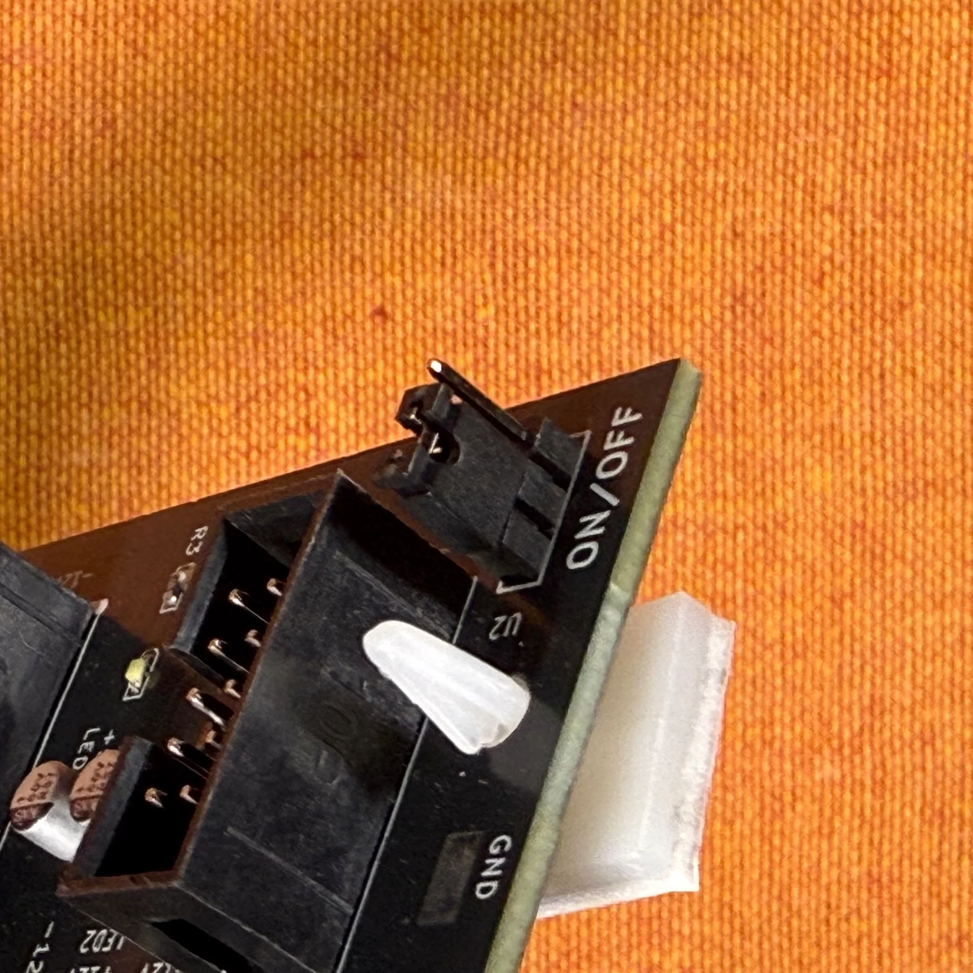
However, this bus board includes a built-in +5V voltage supply feature. To use this feature, switch the toggle on the left end of the board to the ON position as shown below. (It is set to ON at the time of shipping.)
Power Input via Faston Terminals
The zudo-bus can also receive power through the terminals on the right end of the board, as an alternative to the 10-pin connector. When using these terminals, please use protective covers as shown in the photo below to prevent the terminals from touching each other.
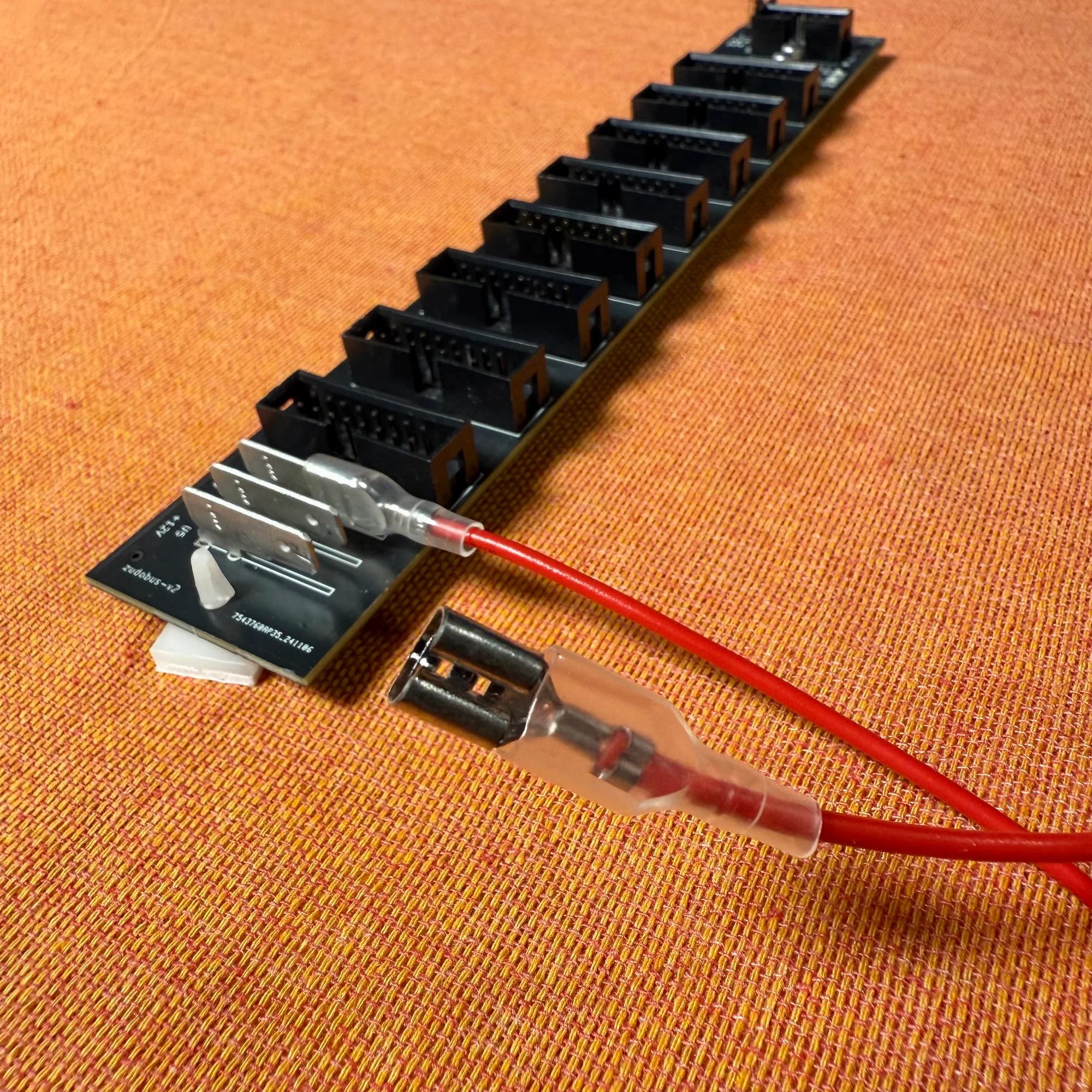
These terminals are provided for achieving noise-free power delivery. Standard Eurorack power ribbon cables consist of bundles of thin copper wires, and when the current flowing through each individual wire increases, there’s a possibility that the cable cannot adequately supply the current demanded by modules.
For this reason, using thicker copper wire at the point where current from many modules converges can help reduce noise generation compared to using power ribbon cables alone. Faston terminals allow the use of thicker gauge wire.
For terminal dimensions, please refer to TE Connectivity 1217754-1.
About Power Supply
This case does not include a built-in power supply, so you’ll need to prepare one separately. The following two power supply modules are readily available domestically:
Included Items
The following items are included with this product. Cables are not included and must be purchased separately.
- Pre-built version
- Fully assembled bus board
- DIY kit
- PCB with SMD components pre-assembled
- 10-pin (2x5) box header x 1
- 16-pin (2x8) box header x 8
- Mounting feet x 2
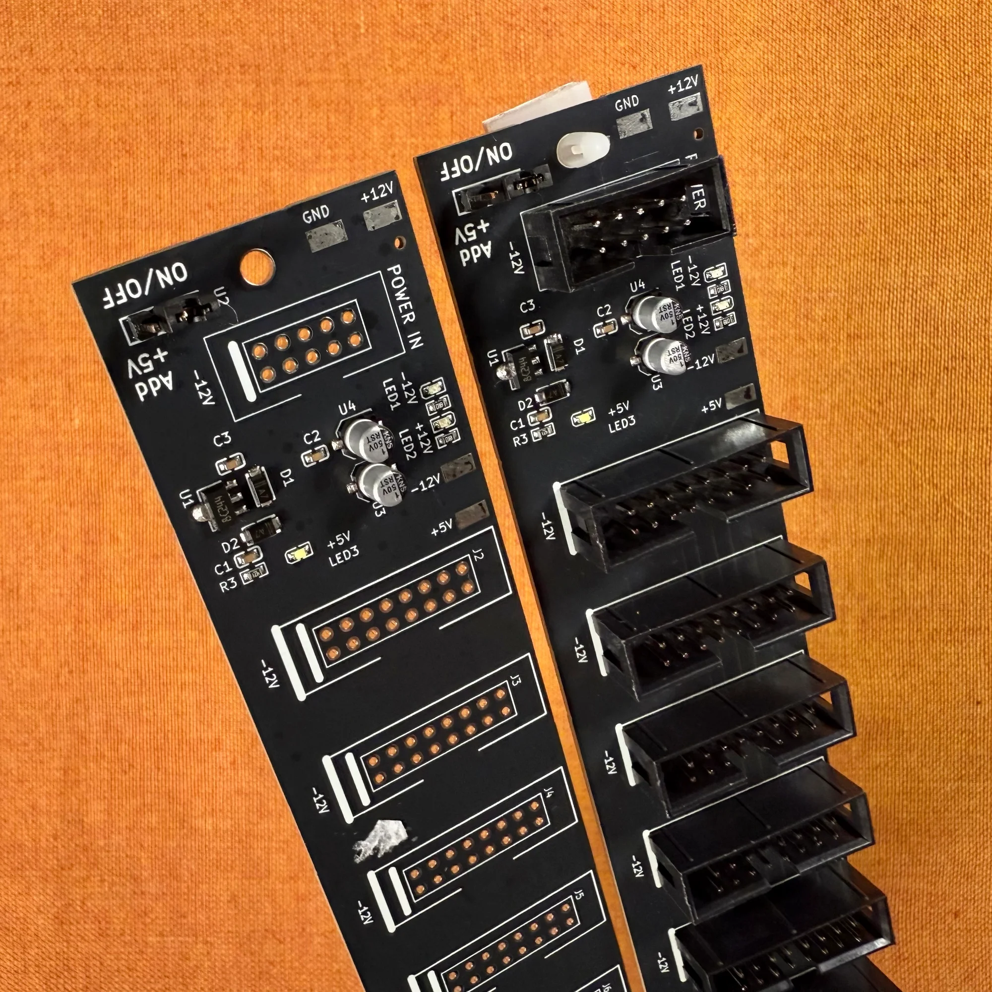
DIY Kit Assembly Instructions
This DIY kit simply requires soldering box headers, making it a low-difficulty project suitable for DIY beginners. However, please note the following two points during assembly:
- Box headers have a directional orientation. Make sure the notched side matches the direction marked on the PCB.
- Accidentally bridging pins with solder can cause short circuits, potentially damaging your modules. Before powering on, carefully verify that no pins are connected by stray solder.
I’ve recorded an assembly video and uploaded it to YouTube. As shown in the second half of the video, if you have a multimeter, I recommend measuring the output voltage from the pins after assembly.
Please see below for reference.
モジュラーシンセのDIYとは?
モジュラーシンセサイザーのDIYについて詳しくご存じない方向けに、以下にDIYの導入的なコラムを用意しました。DIYについてご興味のある方、始めてみようと思う方は、是非ご参照いただければと。
また、組み立てに際して不明点や不安な点がございましたら、以下Takazudo Modularのdiscordチャンネルにてお気軽にご質問等、頂ければと思います。
Terms of Use
We accept no responsibility for any accidents or equipment damage resulting from the use of this bus board. Pre-built units are tested as shown in the video above before shipping, but we cannot provide any warranty beyond that. Please purchase with this understanding.
Specifications
- Dimensions: 200mm x 35mm
- Schematic (PDF)
BOM
- 5V regulator
- 1N4007
- Capacitor 1uF
- Capacitor 0.1uF
- Resistor 470R
- Resistor 1K
- LED Red
- LED Blue
- LED White
- signle row 3pin
- welding terminal 1217754-1
- 10 Pin Box Header Connector 2.54mm 2*5pin
- 16 Pin Box Header Connector 2.54mm 2*8pin
That concludes our introduction of the zudo-bus.
We hope you find this helpful.