
We continue the beginner-friendly series on modular synth power supplies. This is Part 3 of the column for those who find modular synth power confusing. Last time, we covered power supply units, bus boards, and AC adapters. This time, we finally get into the modules themselves and explain current draw.
Here are the previous installments:
- Column 005: Modular Synth Power Supply Intro: Part 1
- Column 006: Modular Synth Power Supply Intro: Part 2
- What Does Current Draw Mean?
- Current Draw of Modular Synth Modules
- Understanding Current Draw
- Current Draw by Module: Examples
- Total Current Draw
What Does Current Draw Mean?
In previous parts, we explained that voltage is like the height water falls from, and current is like the amount of water flowing. The flowing energy powers light bulbs, modules, and so on. That makes sense in theory, but what do you actually need to pay attention to when buying a modular synth case or power supply? The two critical factors are: the total current draw of all your modules and the current capacity of your power supply.
Let’s bring back the light bulb once more. We will start our thinking from there. We light a bulb with a 1.5V AA battery.

1.5V is the voltage. We used the analogy of how high the water falls, and the amount of flowing water is the current. For a typical light bulb, a 1.5V battery causes roughly 200mA to 300mA of current to flow. “mA” stands for milliamps, and 1000mA equals 1A (ampere).
So how is this 200mA figure determined?
It is determined by how much the circuit resists the flow of current. The key concept here is not “how easily current flows” but rather “how hard it is for current to flow.” Something in the circuit impedes the flow of current, and this impedance is what we call resistance. Also, the part of a circuit that consumes power — as seen from the power source like a battery — is called the load. In this example, the light bulb itself is the load, and it has a certain amount of resistance.
Using a water analogy: even if you turn the faucet on, if you squeeze the hose really hard, barely any water comes through. The force squeezing the hose is like resistance. The person squeezing the hose represents the load.
The calculation relating these values uses Ohm’s law:
Voltage = Current x Resistance
You may or may not remember this from school, but suppose our light bulb has a resistance of about 7.5 ohms. If we apply 1.5V of voltage, how much current flows? Plugging into the formula:
1.5V = Current x 7.5 ohms
So 1.5V / 7.5 ohms = 0.2A — that’s 200mA! The math checks out.
To summarize what we have covered so far:
- If you squeeze the hose harder (higher resistance), less water (current) flows
- If you squeeze the hose less (lower resistance), more water (current) flows
That is the basic idea.
Current Draw Reference
A battery-powered light bulb draws about 200mA to 300mA. For reference, here are some current figures for common household devices:
- Iris Ohyama Electric Heater 800W: Approx. 8A at 100V
- PlayStation 5: Approx. 3.5A at 100V (peak)
- Wi-Fi Router WSR-3200AX4S-BK: Approx. 1A with 12V AC adapter
- LED Room Light used in Part 1: Approx. 600mA at 12V
The idea that “resistance determines the current” might be easier to grasp if you consider what happens with zero resistance. For instance, in our battery example, what happens if you connect the positive and negative terminals directly with a wire? This is a short circuit, and since there is almost nothing resisting the current flow, a huge amount of current rushes through all at once.
In the faucet-and-hose analogy, this is like releasing the hose completely and blasting water at full force. Starting from this maximum-flow state, you add components that impede the current to produce the exact amount needed to operate your components. Thinking of it this way may make the concept clearer.
Current Draw of Modular Synth Modules
In modular synthesis, each module has a specified current draw that is usually listed in its specifications. We include this information in most of our product pages on this website, but if you want to quickly check the current draw of your own modules, ModularGrid is probably the fastest reference:
This website is a database of modular synthesizer modules, maintained by manufacturers and DIY builders who register their products when they release something new.
For example, looking up the ADDAC112 VC Looper & Granular Processor, which we carry at our shop, shows:
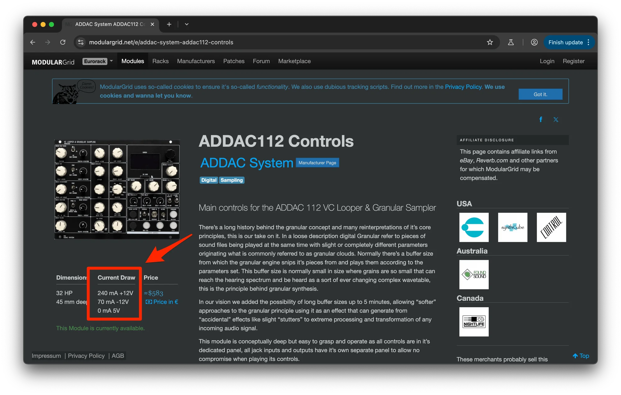
The “Current Draw” field lists:
- 240 mA +12V
- 70 mA -12V
- 0 mA 5V
This means:
- It uses 240mA from the +12V rail
- It uses 70mA from the -12V rail
- It does not use +5V
As explained earlier, current is determined by voltage and resistance. In Eurorack modular synths, the voltages are fixed at +12V / -12V / +5V. And the components inside each module are fixed. So from:
Voltage = Current x Resistance
the current draw is determined for each module. And this current draw varies from module to module.
You do not need to think too deeply about this — the current draw is simply listed in the module’s specifications, so just note roughly how much each module uses.
The reason I bothered explaining resistance is to help you understand that since each module has fixed components with inherent resistance, and the voltages are fixed (+12V / +5V / -12V), the current draw is essentially fixed for each module. Some modules use a lot of current, and some use very little — it depends on how the module is built.
Understanding Current Draw
It is important to remember that the current draw figures are not perfectly precise — they should be treated as reference values.
For example, imagine a very simple module that only produces a sine wave while a button is held down. In such a module, the circuit only connects and draws current when the switch is pressed (assuming a very simple design). Until the button is pressed, almost no electricity is flowing, so the current draw would be close to zero.
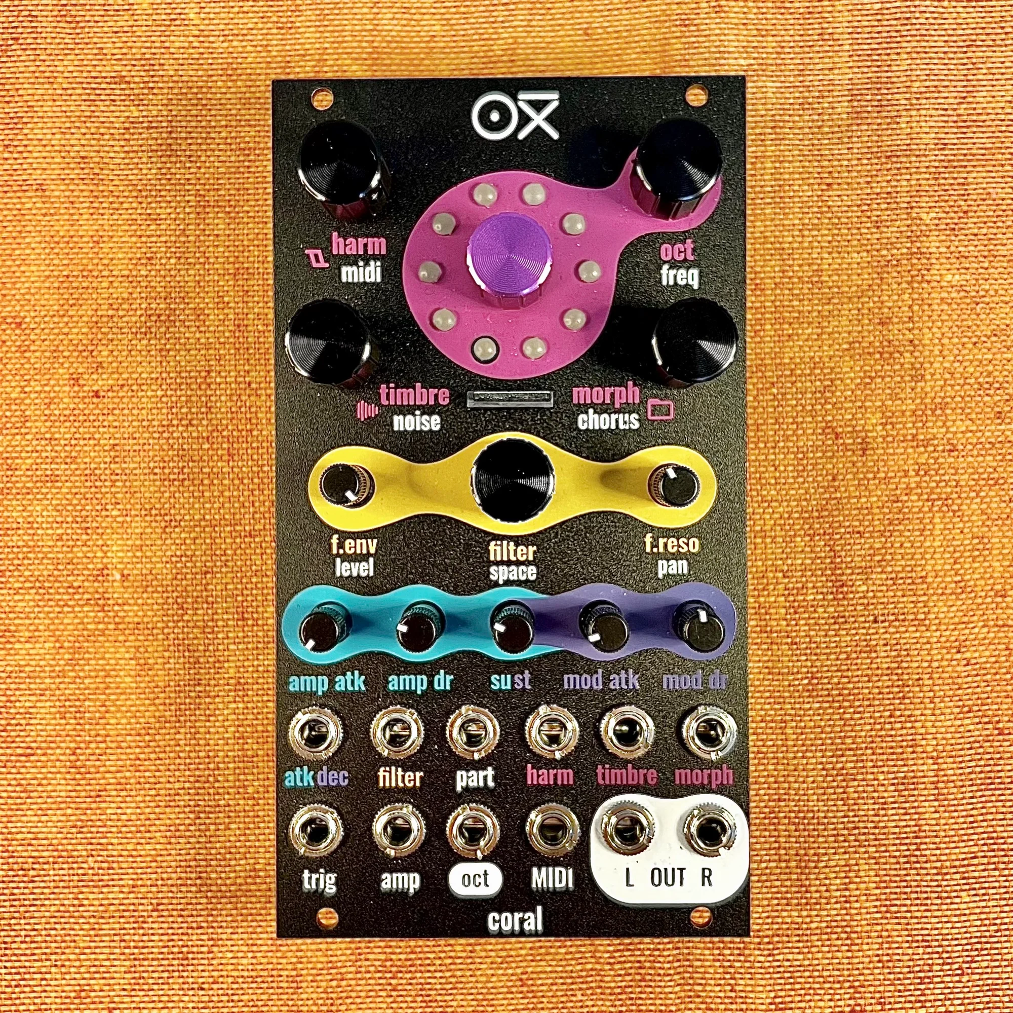
However, modules built around digital ICs are a different story. The ADDAC112 mentioned above, as well as products we carry like Vector Wave and OXI Coral, are modules where an OS-like software running inside an IC boots up when powered on and handles audio processing. These types of modules consume current continuously, even when they are not producing sound. Think of it like a computer that keeps running even when the monitor is off.
Additionally, the current a module draws fluctuates constantly depending on the amplitude of the waveforms it generates, LED brightness, the types of effects being applied, and many other factors. So it is difficult to say definitively “this module always uses exactly 100mA.” The figure can only be stated as an approximation — “it draws roughly this much.”
In practice, how do module makers measure the current draw figures they post on ModularGrid? Lighting a single light bulb makes it easy to calculate, but with a real module and its complex circuitry, it is more practical to measure directly. I imagine most builders connect a multimeter between the power supply and the module, push the module hard in its most power-hungry use case, and measure the current that way, rather than trying to compute theoretical values.
So even if a module’s specs say 200mA, it might actually peak at 300mA under heavy use, or average only around 100mA. It is best to keep that variability in mind.
Current Draw by Module: Examples
How much current do individual modules actually draw? Here are some modules we carry, selected to include a mix of different types:
| Manufacturer | Module Name | +12V | -12V | +5V | Width |
|---|---|---|---|---|---|
| ADDAC System | ADDAC701.REV2 VCO | 60mA | 60mA | 0mA | 8HP |
| ADDAC System | ADDAC106 T-Noiseworks | 40mA | 40mA | 0mA | 8HP |
| OXI Instruments | OXI Coral | 110mA | 10mA | 0mA | 14HP |
| AI Synthesis | Stereo Matrix Mixer | 20mA | 20mA | 0mA | 18HP |
| AI Synthesis | AI017 Low Pass Gate | 19mA | 17mA | 0mA | 8HP |
| Weston Precision Audio | AD110 | 75mA | 35mA | 0mA | 16HP |
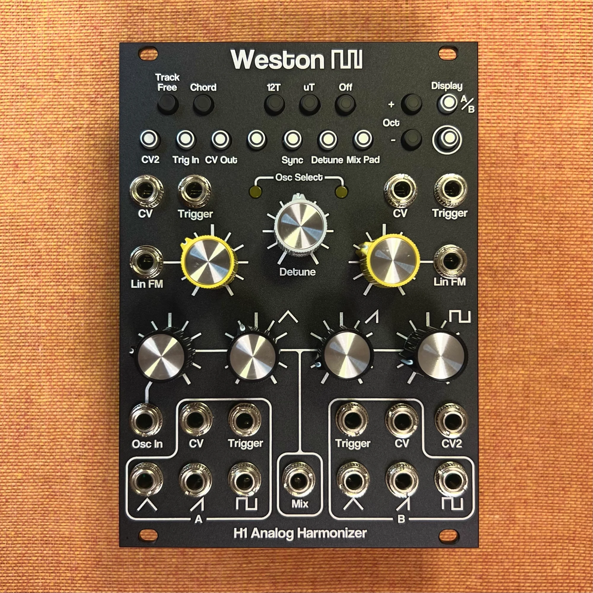
| Weston Precision Audio | H1 Analog Harmonizer | 200mA | 85mA | 0mA | 18HP |
| RYK Modular | Night Rider | 52mA | 9mA | 0mA | 16HP |
| Meng Qi | DPLPG | 0A | 0A | 0A | 2HP |
Let’s look at what this table tells us.
No Modules Use +5V
In the previous article, we mentioned that +5V is rarely used, and looking at the modules listed here confirms this: very few modules use +5V. This is not because we deliberately excluded +5V modules — they really are that uncommon. In fact, we would have loved to include one here if we could find it among our product range.
Digital Modules Draw More Current
As noted earlier, modules using digital components consume current continuously. These digital modules also tend to have higher current draw.
The module drawing the most +12V current in this list is the H1 Analog Harmonizer, which analyzes the pitch of an incoming waveform and generates harmonically related pitches (third above, fifth above, etc.) to easily create harmonized sounds. It has a menu system for various settings, so it almost certainly contains a digital IC.
The second highest is the OXI Coral, a multi-timbral synth module that can function as a polyphonic synthesizer with various built-in effects. Most of its sound design is handled by software running on a digital IC, enabling a wide range of sounds through advanced processing.
The H1 draws 200mA on +12V, and the Coral draws 110mA on +12V. These two digitally-powered modules are the top consumers in this list.
+12V Current Draw Is Higher Than -12V
Looking at the overall picture, you can see that +12V current draw tends to be higher than -12V. None of the listed modules draw more current on -12V than on +12V.
If you were to put all these modules in a single case, the total current draw would be 576mA on the +12V side and 276mA on the -12V side. The +12V side is more than double the -12V side. The reason so many modules exhibit this pattern is that relatively few components require both positive and negative voltage rails.
Most common electronic components operate from a single-direction current source. The ICs used in the digital modules mentioned above, microcontrollers like Arduino for complex tasks, small displays, LEDs — all of these, when designed straightforwardly, only need the positive voltage rail, which is why more current is drawn from +12V. Light bulbs also operated from a single direction of current flow, remember?
On the other hand, when an oscillator IC needs to generate a sine wave, for example, it must produce voltage swings in both the positive and negative directions equally. Such components need both the positive and negative voltage rails to function correctly. That is why they also draw from the -12V side.
In modular synths, while there are many components of this latter type, everything else runs on the +12V rail by default. So +12V current draw ends up being relatively higher overall.
Some Modules Draw Zero Current
You may have noticed that the last module in the table, DPLPG, has zero current draw across all rails. It does not even have power connector pins. Yet it works perfectly. Why? Such modules are called passive modules, and they are designed to operate without any external power.
How is that possible? Simply put, the circuit uses no components that require an external power supply. In the case of this DPLPG, it is a module that simply attenuates an incoming signal. If the input is a sine wave with a swing of plus or minus 5V, the output is a signal at or below that voltage level.
The circuit has the characteristic low-pass gate behavior of filtering higher frequencies more aggressively, which is achieved using the natural properties of a capacitor — no external power needed. Without going into excessive detail, the point is: if a module has a simple enough structure that it does not need external power, it can work without any power connection at all.
The most common example you are likely to encounter is the passive multiple. At our shop, AI Synthesis: AI001 Multiple is one such product.
Total Current Draw
So each module has its own current draw — understood. But what really matters when thinking about power is the total current draw of all your modules combined. As mentioned briefly earlier, adding up all the current draws from the table gives us:
- +12V: 576mA
- -12V: 276mA
- +5V: 0mA
In the previous installment, we explained that the PSU supplies power to each module in parallel through the bus board. Using the diagram from Part 1, this is like supplying water to run each module:

So what should you do? You need a power supply unit with sufficient current capacity to cover the total demand of all your modules.
And since the current draw values in module specs are only reference figures, if we estimate with some headroom for the modules listed above, we would need roughly:
- +12V: 800mA
- -12V: 400mA
- +5V: Not needed
A PSU capable of supplying this much current should be more than sufficient.
This ran longer than expected, so we will continue next time…! Next time, we will look at the power supply unit’s current ratings and some things you need to watch out for.
The next installment is ready. Please see below.