In this series, I'll be introducing modules from Weston Precision Audio.
Weston Precision Audio is a boutique maker based in Portland, Oregon. Designer Devin handles all of the design and manufacturing himself, and his commitment to the precision and quality of analog circuit design comes through in every module. High stability thanks to temperature-compensated VCA modules, accurate tracking over 7+ octaves, through-zero FM — the kind of serious specs that hold their own against the big names, all packed into compact modules.
The brand isn't widely known in Japan yet, but once you actually use these modules, you really start to feel the appeal of well-designed analog circuitry. In this series, I'll be walking through the Weston Precision Audio lineup in Japanese, based on the official demo videos and manual. If you're looking for new options in the modular world, this is a maker worth knowing about.
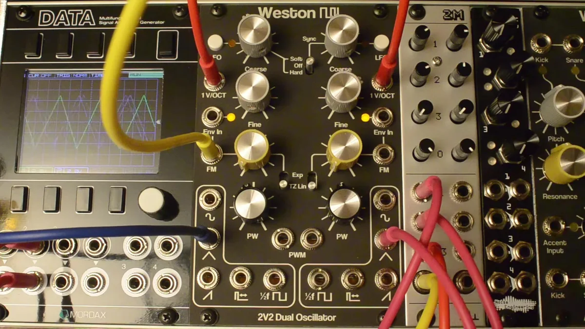
For EP.1, we'll cover the dual analog oscillator, the 2V2.
Takazudo Modular publishes manuals and related documents with Japanese translations. See the links below.
- What Is the 2V2?
- Spec Summary
- The Five Waveform Outputs
- FM (Frequency Modulation)
- Env In — Built-In VCA for FM
- Sync (VCO B → VCO A)
- Cross-Modulation + Sync
- LFO Mode
- Pulse-Width Modulation (PWM)
- CVB Jack Normalization
- Practical Patching Tips
What Is the 2V2?
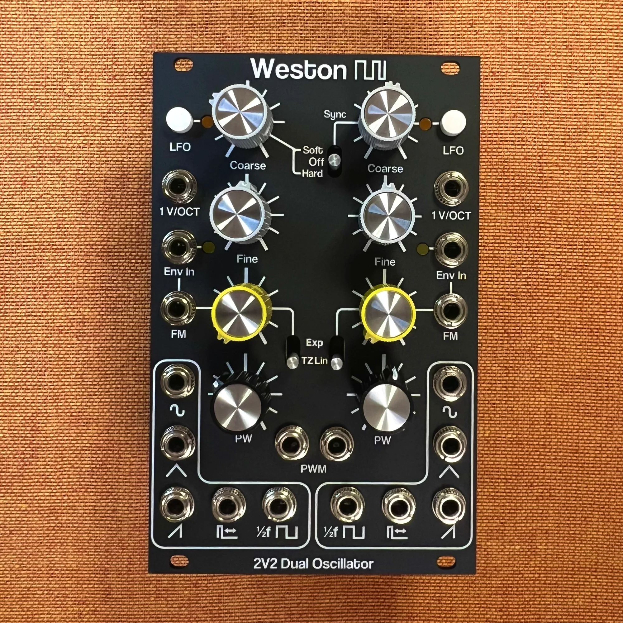
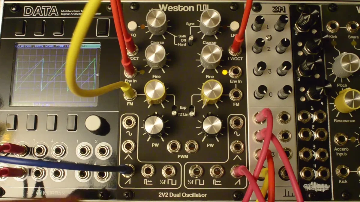
The 2V2 is a dual oscillator module that packs two analog triangle-core VCOs into 16HP. It's the successor to Weston Precision Audio's first module, the original dual VCO, with substantially expanded features.
The two VCOs are identical in configuration, each offering five waveform outputs: triangle, sine, sawtooth, pulse, and sub-octave square. On top of that, each VCO supports both Exponential FM and Through-Zero Linear FM, and even includes a built-in VCA that lets you control FM depth with an envelope or other CV.
Spec Summary
| Item | Specification |
|---|---|
| Size | 16HP |
| VCO Topology | Triangle core × 2 |
| Waveform Outputs | Triangle, sine, sawtooth, pulse, sub-octave square (per VCO) |
| Inputs | V/Oct, FM, Env In (per VCO) |
| FM Type | Exponential / Through-Zero Linear (switch-selectable) |
| Output Level | Approx. 10Vpp (each waveform) |
| Tracking | 7+ octaves |
| Power Draw | +12V: 115mA (typ) / -12V: 85mA (typ) |
| Special Features | LFO mode, soft / hard sync (VCO B), built-in VCA for FM |
The Five Waveform Outputs
Each VCO offers five waveform outputs. The demo video walks through them in order right at the start.
Triangle

This is the triangle taken straight from the VCO core. It has few harmonics and a soft, gentle tone.
Sine

An approximate sine wave, generated by running the triangle through an overdriven matched differential pair circuit. The purest of the five tones, and excellent as either a carrier or a modulator for FM.
Sawtooth

A sawtooth derived from the triangle and square waves. It contains every integer harmonic, giving you a bright tone that suits leads and basses well.
Pulse

The pulse width is adjustable from 0% to 100% via the PW pot, with the center position landing at 50% (a square wave). Send a modulation signal into the PWM input and you can shape the timbre dynamically.
Sub-Octave Square (1/2f)

A square wave that runs at half the frequency of the other outputs. Handy when you want to add an octave of thickness underneath.
FM (Frequency Modulation)
One of the 2V2's standout features is the FM section built into each VCO. The switch next to the FM input lets you toggle between Exponential FM and Through-Zero Linear FM.
Through-Zero Linear FM (TZFM)
"Through-Zero Linear FM" sounds intimidating, but there's really only one point you need to grasp: it's the kind of FM where the pitch doesn't fall apart even when you modulate it deeply.
The fastest way to see what's different is to look at it. Below are two oscilloscope-style traces, both with the same carrier (sawtooth), the same modulator (a slow sine), and the same modulation depth. The only thing that changes is the FM type. The red highlighted region marks the point where the modulation dives the deepest.
With regular linear FM, the carrier simply "stops" in that region. You can see the sawtooth's rise and fall freeze into a flat line. That's what chokes the timbre and throws the pitch off.

With TZFM, instead of stopping, the carrier reverses direction and keeps going. You should be able to see the sawtooth flip into a downward slope and then return to going upward again.

It's this "never stops, just flips and keeps running" behavior that lets TZFM hold the carrier's pitch together even at deep modulation depths. You can hear it in the demo video too — even with quite heavy TZFM, the pitch stays firmly intact.
A bit more on how it works
To get slightly more technical: the relationship between modulation voltage (V_mod) and instantaneous frequency (f) traces out a straight line like the one below. With TZFM, deep modulation drives the frequency right through 0Hz and into the negative region — and that "negative frequency" is exactly the phenomenon we just saw, where the waveform runs backwards.

The purple band shows the modulator's swing, and the blue marker at the left end is the midpoint of the output frequency across that range. With TZFM, that midpoint lands exactly on the base frequency f₀ (the white circle) — which is the mathematical reason the average pitch doesn't drift, no matter how deep you go. The manual's oscilloscope images show the same thing: with TZFM, the carrier's fundamental stays well balanced.
Exponential FM
This is the more conventional flavor of FM, where the pitch shifts exponentially with the modulation signal. It produces wilder, less predictable sounds than TZFM, and is well suited to percussive effects and noise-like timbres.

Plot the Exponential FM transfer curve on the same axes as TZFM and the character jumps out. The curve only approaches 0Hz asymptotically — it never crosses below — while shooting way upward on the other side. That top-to-bottom asymmetry is the reason "the pitch ends up drifting upward" when you modulate deeply: you can see the orange marker on the left (the midpoint of the output frequency for a ±1V modulator) sitting clearly above the base frequency f₀.
FM Amount Pot
The attenuator next to the FM input lets you dial in how much FM gets applied. This is where you fine-tune the strength of an external modulation signal. Turn it to 0% and the modulation amount goes to zero — the carrier passes through unchanged whether you're set to TZFM or Exponential.
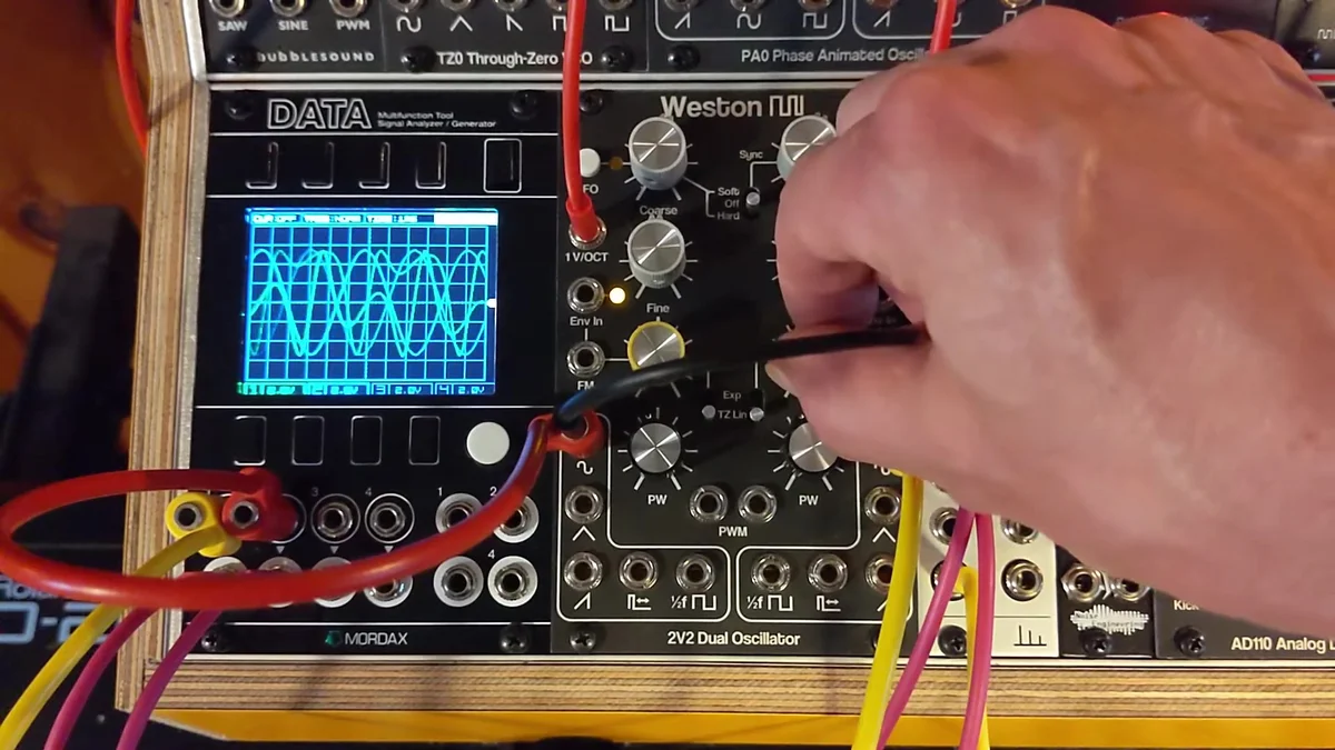
Env In — Built-In VCA for FM
One particularly unique feature of the 2V2 is the Env In input on each VCO. Feed a unipolar signal in here (0–5V, from an envelope or similar) and you can dynamically control how strongly the FM is applied.
The figure below visualizes what Env In does. The top trace is the modulator — a constant-amplitude sine wave. On its own, it would just keep applying the same depth of FM forever. The middle trace is an envelope (attack → decay shape) fed into Env In, and it controls how much of that FM actually reaches the carrier, over time. The result is the bottom trace: the carrier's FM gets deep right as the envelope rises, then fades back to a clean carrier waveform as the envelope releases. That's how you get dynamic FM sounds without needing an external VCA.

In other words, you can make the FM get deeper the moment a key is pressed and fade away on release — all without an external VCA. The same feature appears on Weston Precision Audio's TZO module too, and it really opens up the sound-design space for FM patches.
In the demo video, Devin himself notes that "with one or two 2V2s, you can build your own FM algorithms in the analog world — and they don't take up any space." Being able to recreate the kind of algorithmic structures familiar from digital FM synths, fully in the analog domain, is genuinely appealing.
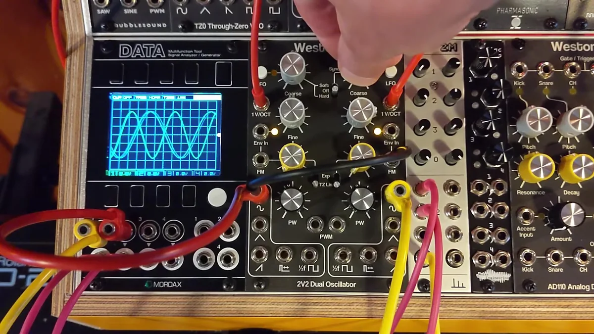
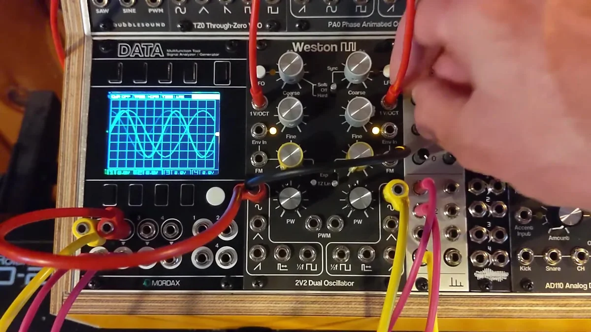
Sync (VCO B → VCO A)
The right-hand VCO (VCO B) can sync to the left-hand VCO (VCO A). A three-position switch controls it.
Soft Sync
Flip the switch up and VCO B's triangle wave inverts on every positive zero-crossing of VCO A. Change VCO B's pitch and you get a distinctive sound where the harmonic structure shifts around. In the demo video, you can see the blue waveform (VCO B) flipping on the oscilloscope.
In the figure below, the top trace is VCO A (the master), a sine wave, with its positive zero-crossings marked by yellow vertical lines. The middle is VCO B's triangle running free (no sync), and the bottom is VCO B with soft sync engaged. On every trigger, the triangle's polarity flips and it continues in the new direction from there.

Hard Sync
Flip the switch down and VCO B's capacitor is reset to zero on every positive zero-crossing of VCO A. The result is a more aggressive, sharper-edged sync sound — ideal for classic sync leads.
Same layout as before: VCO A on top, VCO B free-running in the middle, and VCO B with hard sync on the bottom. Unlike soft sync, every trigger snaps VCO B's phase all the way back to zero — you can see the sawtooth get "cut off" mid-cycle and start over from the beginning. That's the source of hard sync's aggressive, biting sound.

Cross-Modulation + Sync
A second demo video covers more advanced techniques, combining TZFM with sync.
Plain TZFM (no sync)
The basic setup: the left VCO (VCO A) modulates the right one (VCO B) via FM. Even as you change the modulator (VCO A)'s pitch, you can hear the carrier (VCO B)'s base pitch stay firmly in place. Solid TZFM performance, all the way up to fairly high frequencies.
Soft Sync + TZFM
Add sync and the character of the TZFM changes. Modulator pitch changes now affect the overall pitch more strongly, and changing the carrier's pitch shifts the FM character itself. You can see inflection points on the oscilloscope where the waveform flips, which makes the effect of soft sync visible.
Hard Sync + TZFM
Switch to hard sync and things get even more aggressive. Because the sync resets rather than inverts, you get sharper edges in the tone.
Reverse Cross-Modulation
The second half of the demo video (from 2:57) shows a reversed patch: VCO B modulates VCO A, while VCO B is synced to VCO A's frequency. This sets up a kind of feedback loop and produces some genuinely chaotic sounds.
LFO Mode
Each VCO can switch to LFO mode at the press of a button. In LFO mode, it runs at roughly 0.015× the normal frequency — perfect as a low-frequency modulation source.
In the demo video, you can see the amber LED light up when the button is pressed, switching the VCO from audio rate down to modulation rate. Since the module is dual, you can use them as a pair of LFOs.

Pulse-Width Modulation (PWM)
Each VCO's pulse output has a PW pot for adjusting pulse width from 0% to 100%. The center position lands at 50% — a square wave.
There's no attenuator on the PWM input, so you'll need to adjust the level externally. Patch an LFO or envelope in and modulate the pulse width over time, and you get a chorus-like thickness to the tone.
In the figure below, the top trace shows PW = 50% (square wave), the middle is the PWM control signal (an LFO sine wave), and the bottom is the pulse output with PWM applied. Following the voltage at the PWM input, the duty cycle (the ratio of time spent high vs. low in each cycle) shifts over time.

CVB Jack Normalization
On the back of the 2V2's jack PCB, there's a solder jumper that controls how VCO B's V/Oct jack is normalized — that is, what happens when nothing is plugged in.
0V (default): With nothing connected to VCO B's V/Oct, 0V is fed in. VCO B free-runs.
CVA: With nothing connected to VCO B's V/Oct, VCO A's V/Oct signal is also routed to VCO B. Handy when you want a single pitch CV to control both VCOs.
Devin uses the default 0V setting in the demo video, so you can see VCO B start to free-run whenever he unplugs its V/Oct cable.
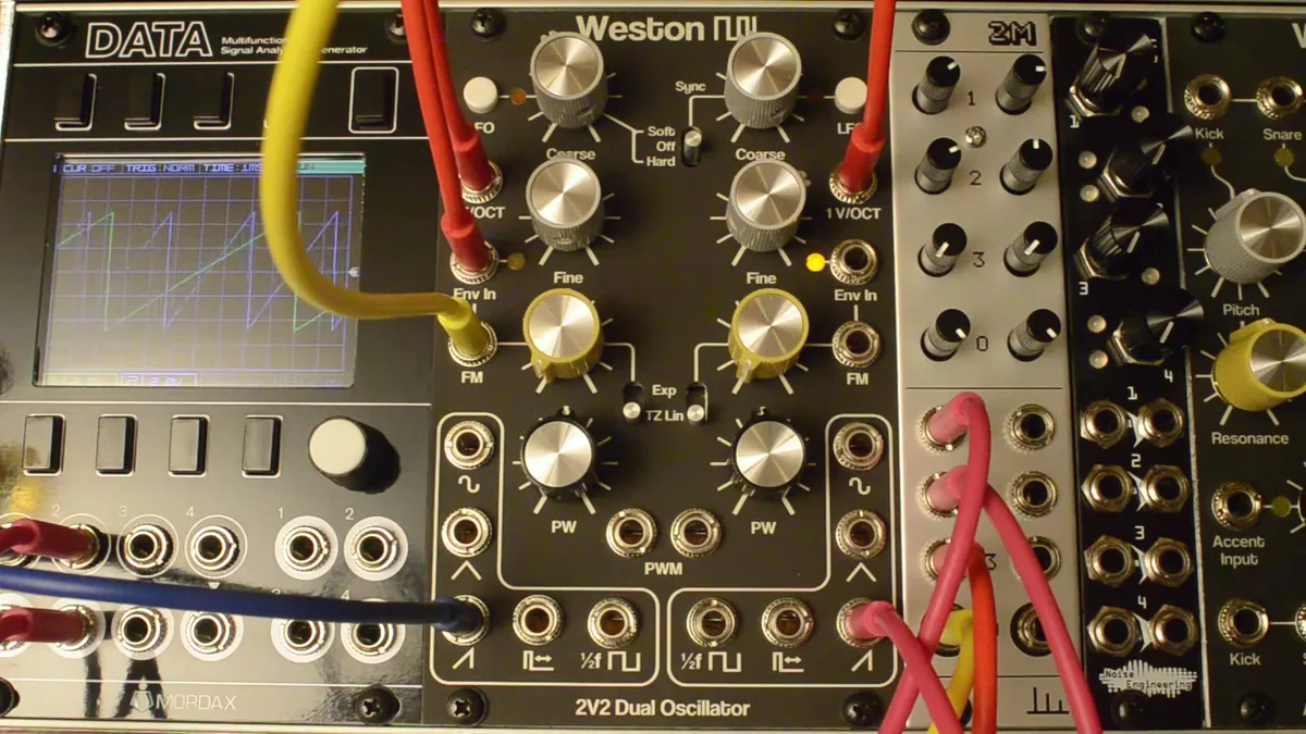
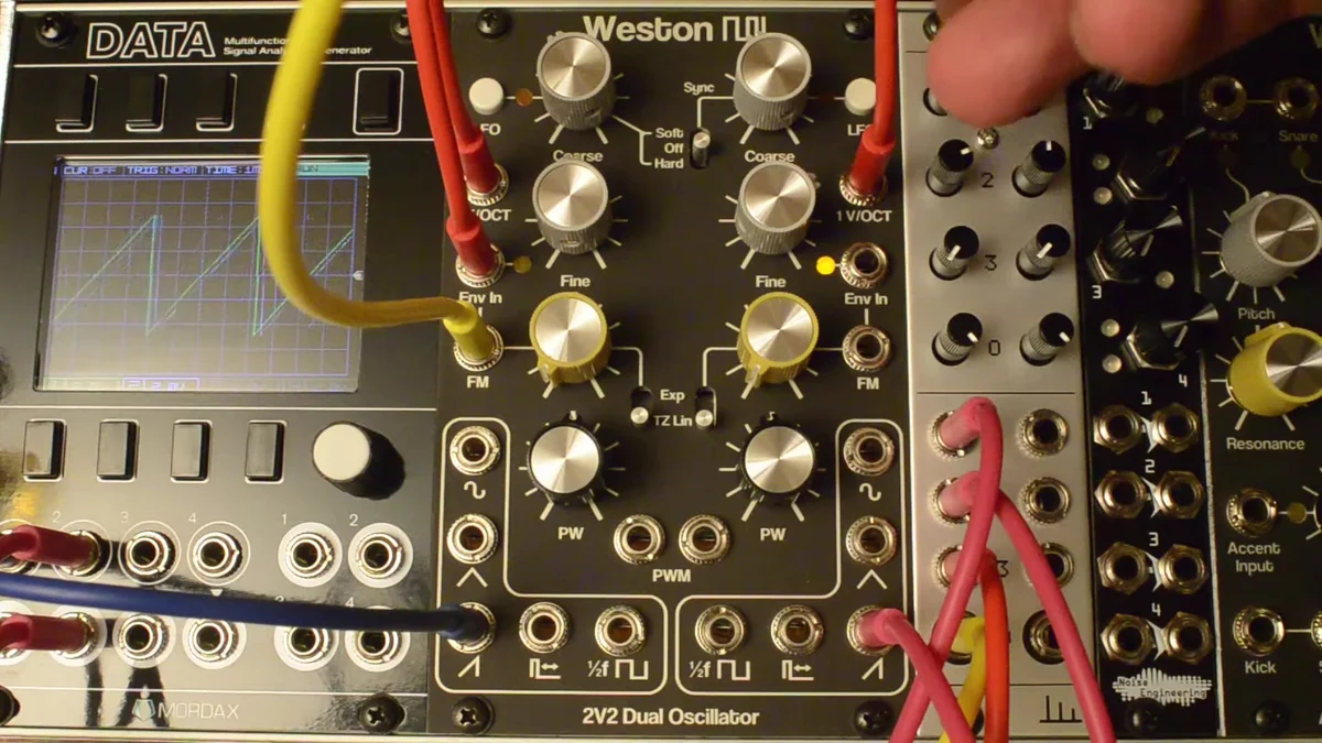
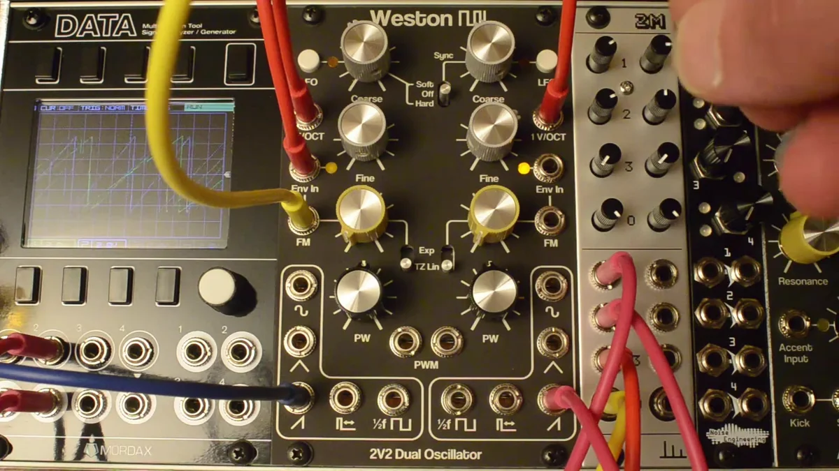
Practical Patching Tips
Basic dual-VCO patch
The simplest use is to send the same V/Oct to both VCOs (either via the CVA normalization setting, or with a multiple), detune one slightly, and mix them. This is the classic recipe for that rich, characteristically-analog dual-oscillator tone.
Analog FM synth
Make use of Env In and you can get dynamic FM sounds without any external VCA. Sync the envelope to a keyboard gate, and you can recreate DX7-style behavior in the analog domain — FM that bites in on note-on and fades away on release.
As a modulation source
Switch to LFO mode and you've got two voltage-controlled LFOs. You can even drive the LFO speed externally via the V/Oct input — a surprisingly capable modulation source.
Sync + FM combinations
Combine hard or soft sync with TZFM and you can produce complex harmonic structures that neither VCO could create alone. The cross-modulation patches in the second demo video have a really unique character, so give them a try.